Submitted by DIYouware on Mon, 09/22/2014 - 19:19
Last week we were doing more testing on laser focusing.
The first idea was to focus the laser on four reflecting focus points we glued under the glass. The robot automatically moves the toolhead to those focus points and take four focus measures. Then it uses them to extrapolate the data to the rest of the PCB so it can accurately focus the laser while rastering the PCB picture. But we had some problems with the glass thickness. We were using an inadequate 2mm glass and we had to change to 1.5mm glass which works better. But even with the new glass we were not satisfied because the focus points were too far from the PCB corners so the measures were not accurate.
If we wanted to improve the focus accuracy we had to focus on the PCB corners. This is not a problem because the PCB is reflective enough to focus directly on it but as always happens appeared two secondary effects.
First we “paint” four blots on the PCB dry-film because the UV laser sensitizes it on the places it focuses. Second we have to focus through the glass and the solar film. Remember that we use the solar film to filter the UV rays and protect the PCB from the “halo” effect produced by the pickup lens. The filter is good while we printing but diminish performance when we focus. So we were again in a dead-end alley.
I think we found a solution: the red laser.
The PHR-803T is fantastic. It has three laser diodes: one in the infrared band for reading CDs, one on the red band for DVDs and one on the near UV band for HD-DVD/Blu-ray. When we hacked the pickup we didn’t paid too much effort on the red lasers because we were focus on sensitize the dry-film with UV light but I think we are going to use the red one now.
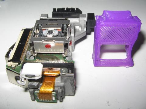
Use the red laser to focus has some advantages:
Submitted by DIYouware on Fri, 09/12/2014 - 16:27
We successfully finished the 3D printing tests and now we are focus on the Laser Toolhead, but first let me tell you how important is to level correctly the fixture plate.
As I said in the last post we developed some code to test the bed auto-levelling algorithm. This algorithm is in the firmwware and maintains the platform perfectly levelled while the robot is working.
The test is based on focusing the laser on the platform. We use the laser to measure how far is the platform in 36 surface points distributed on a 6x6 matrix.
To check if the bed auto-levelling algorithm works fine we did the test after and before leveling the platform.
These are the results:
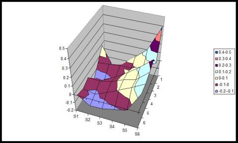
Fig. 1 – Test results without bed auto-levelling
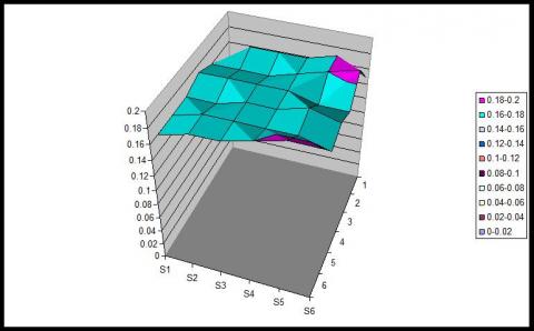
Fig. 2 – Test results after auto-levelling calibration
Submitted by DIYouware on Sat, 09/06/2014 - 23:42
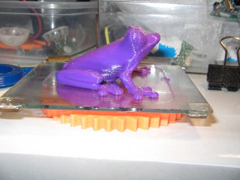
Just show you our first 3D object printed with the robot. It took aprox. one hour and the quality is really good.
Submitted by DIYouware on Fri, 09/05/2014 - 20:00
After some days of vacation we have continued the robot testing.
Last days we have been working on the 3D Printing Toolhead. We did several printing tests with good results and we found the speed limits of the machine which are aprox. 3500 mm/min (when 3D printing)
Also we improved the server side software. We added functionality to control the 3D printing extruder and the hot-end temperature.
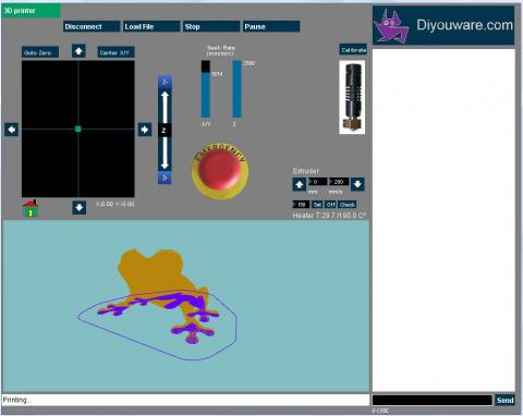
We also developed a firmware algorithm to test how efficient is the auto-levelling algorithm. We had some doubts about if really the algorithm worked fine but they were unfounded because it does and the platform is always levelled with a precision of less than 0.01 mm.
Submitted by DIYouware on Wed, 07/09/2014 - 22:05
Some days ago we described how we designed the bed to fulfil all the requirements. In this way we built all the components of the bed in order to test if the complete system works with the different tools and finally it looks like this:
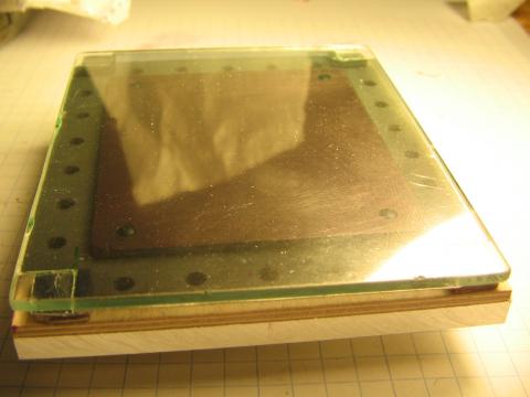
You can see in the picture the different removable layers:
Submitted by DIYouware on Thu, 07/03/2014 - 19:51
We continue with the printer testing in rastering mode.
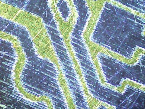
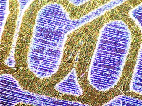
Every time we obtain better results.
We also designed a bus connector case.
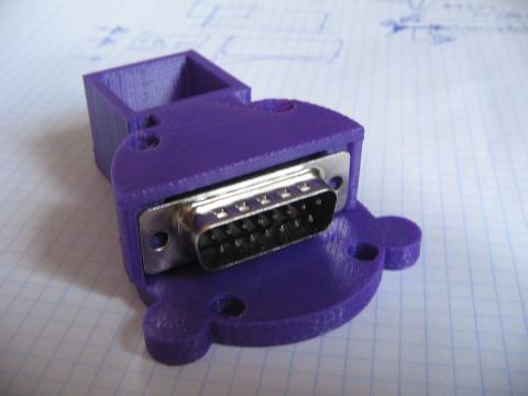
We are using a 15 wire cable and a DB15 connector for carry all the signal and power lines that any tool might need. The idea is that every toolhead will use that DB15 connector with a standard pinout. In this way, It will be easy toolhead substitution.
Submitted by DIYouware on Tue, 06/24/2014 - 17:37
The following is a list of preliminary specifications for the new robot:
Working area
70x80x80mm (X,Y,Z). We reduced it considerably to an Arduino Shield size. In fact sometimes we call the robot “The Arduino Shield Maker”. We reduced it because we preferred to do something small but precise. Rarely all of we create big circuit boards but if you need it you can always split the circuit in two or more modules. Reducing the working area has some advantages: the robot is cheaper, more precise, robust, smaller and more manageable.
Motion
MKII is powered by three Nema 17 motors and Acme screws. We substituted the timing belts we used in MKI in order to eliminate vibration and resonances. It was mainly the solution and now the laser draws on the PCB with a stable beam without any mechanic disturbance.
Speed
We can go as fast as 1200-1500mm/min. We think it’s enough for our purposes. The Acme screw pitch set the limits. The robot can go faster upgrading the screws to ones with more pitch but at a price.
Submitted by DIYouware on Thu, 06/19/2014 - 14:06
Today we received the aluminium fixture plate a friend of mine made. It's fantastic.
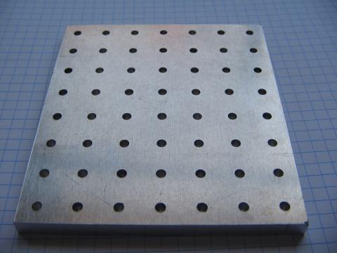
One of the things we have learned on the development of MKII is how important is to fix well the PCB to the printing bed.
We tried different solutions:.....
Submitted by DIYouware on Tue, 06/17/2014 - 21:29
Today we continue with the printing tests in rastering mode with very good results.
The process of printing in raster mode begins on Eagle CADSoft which is the tool we use to design the PCBs.
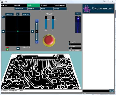
Once the board is finished then we export it to PostScript format (Device: PS in the Eagle’s CAM processor) and open it with DiyouRun V2.0.
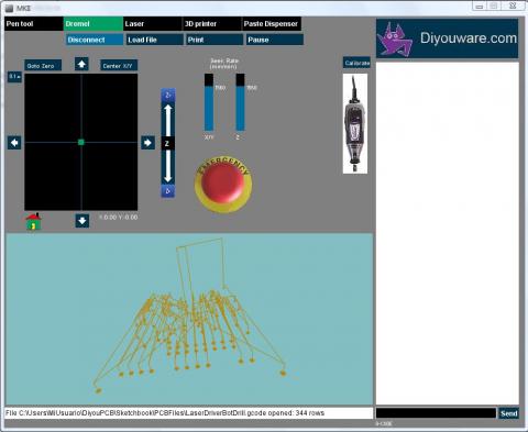
DiyouRun has change a lot since last version and now it has a new look and feel adapted to the new robot.
Submitted by DIYouware on Sun, 06/15/2014 - 18:32
Some people asked us to describe in more detail the capabilities of MKII.
Well, the robot is very versatile so it can do a lot of things. All depends on the toolhead you install on it.
We call “toolhead” the tool adapter needed to install a tool in the robot, for example a laser tool. Once you have the toolhead it is very easy to use the tool. Just uninstall any previously installed toolhead, connect the new one, and use it.
We already designed some toolheads but...
Pages