Skip to main content area
Home
  • English
  • Español
  • Get it
  • Build it
  • Use it
  • Blog
  • DiyouPCB
    • Get It
    • Build
    • Use
    • Improve
    • Gallery
    • Downloads
  • Contact
  • About us

You are here

Home

Laser Focus improvement

Submitted by DIYouware on Sun, 03/27/2016 - 20:56

Stephan R. from Germany sent us an improvement on the firmware focus code.

It's related to the way we reset the ADC every time the interrupt vector is invoked. Below you can see the code affected including the modification (commented lines in red).

Basically, we were re-starting the conversion using the sentence ADCSRA |= 1<<ADSC and really it is not needed because we configured the ADC to auto-trigger on the init function.

Although we have been focusing without any problem since we wrote that code we tested the modification and we saw that the driver can focus in the same way and probably better.

Stephan said he discovered it because his prototype had problems to focus and when he removed the lines mentioned the driver started to focus well. Probably this different behaviour between prototypes is produced by electric noise on the FE signal and using this modification the firmware is more robust and detects easily the s-curve needed for focusing. Stephan also confirmed us that once focused the laser prints correctly at 600dpi so it means it is really focused.

We will continue to test this improvement but if you experimented difficulties while focusing try to comment those lines (in red). Then compile it and upload the code to the Arduino. You will find the code at focus.cpp file on TwinTeethFirmware.

Thanks very much Stephan!!

/**
 ** Interrupt vector
 **/
ISR(ADC_vect) {//when new ADC value ready
  static int FEVal;
  static int FEtimeout;
  //ADCSRB = 0;
  //ADMUX = ((1 << REFS0) | ((FE_SIGNAL_PIN-PIN_A0) & 0x07));


  // State machine
  switch (fe_state){
  case FE_WAIT_ST:
    FEtimeout=0;
    break;
  case FE_AMPLITUD_ST:
    //ADCSRA |= 1<<ADSC; // Start conversion
    FEVal = ADC;
    if ( FEVal > fe_max_val)
      fe_max_val = FEVal;
    if (FEVal < fe_min_val)
      fe_min_val = FEVal;
    break;
  case FE_FOCUS_ST:
    //ADCSRA |= 1<<ADSC; // Start conversion
    FEVal = ADC;
    if (abs(REF_FE_VALUE - FEVal) > fe_amplitud/FE_NOISE_DIVIDER){
      FEtimeout=0;
      fe_state = FE_SCURVE_ST;
    }
    else if (FEtimeout++ > FOCUS_TIMEOUT){
      fe_state = FE_ERROR_ST;
    }
    break;
  case FE_SCURVE_ST:
    //ADCSRA |= 1<<ADSC; // Start conversion
    FEVal = ADC;
    if (abs(REF_FE_VALUE - FEVal) <= fe_amplitud/AMPLITUD_DIVIDER){
      fe_focus_pos = fe_servo_pos;
      fe_state = FE_FOCUSED_ST;
    }
    else if (FEtimeout++ > FOCUS_TIMEOUT){
      fe_state = FE_ERROR_ST;
    }
    break;
  case FE_FOCUSED_ST:
    break;
  case FE_ERROR_ST:
    break;
  }
}

  • Read more about Laser Focus improvement
  • Log in or register to post comments

New software release

Submitted by DIYouware on Sun, 12/27/2015 - 21:57

We have been working during Christmas vacations to finish the new release of the software. We modified all the software tool chain to include new functionality, adapt the software to new library versions and fix some bugs.

These are the changes:

TwinTeeth Firmware V2.1

  • New functionality to fire the laser using Z or E axis.
  • New G81 command for drilling and filling blind vias.
  • Minor changes on rastering laser printing.

TwinTeehMC 2.3

Refactoring and new Processing version support

We refactored the server side software to re-write some code and also support new versions of Processing and ControlIP5.

Now we support the following versions:

  • Processing 3.0
  • ControlIP5 2.2.5
  • ghost4j-0.5.1. 
  • GhostScript 9.16

New 0.05mm option added to the Jog keypad

When you click on the arrows at the KeyPad sides, you manually move the platform  the millimetres shown on the top-left corner of the pad. If you click there you will see that you can change that number to 0.1,1 and 10mm. In this new version we also add 0.05mm to provides you more precision manually moving the platform.

New Laser plotting and 3D functionality

We added new functionality to the Laser Toolhead tab to allow different ways of printing with the laser.

Last version only supported laser rastering printing. This method has a high resolution because it prints bitmaps at 600dpi, in a similar way a paper printer does, but sometimes it can be time consuming. For this reason we included in this new version the possibility to use the laser for plotting boards. You can use this option to print circuit traces using negative film/boards or to quickly isolate the traces using positive film/boards. It works using the Z axis as the trigger to fire the laser. When the Z axis moves below zero position the firmware fires the laser. When it moves up under zero it turns the laser off. Activate this mode is easy: just push the Plot button, load a valid g-code or HPGL file, focus the laser pushing on the Focus button and run the program. Note that the laser will focus only one time at the centre of the board and not four times on the corners like rastering mode does.

The second method is based on the movement of the E axis and is experimental. We used it to 3D print objects with the laser on UV resin. It consists on fire the laser when the E axis moves. The E axis is the plastic extruder axis of 3D printers. The g-code generated by the slicer programs moves the e-axis when the extruder has to deposit some plastic on the object. Instead of that, we fire the laser to cure the resin. You can use any g-code file generated by 3D printing software like Cura or Slic3R. Just push the 3D button on the Laser ToolHead tab, load a valid 3D g-code file, focus the laser and run the program.

New board offset fields

We added x,y board offset fields to avoid the issue of centring the board while using Eagle’s light edition.

Basically we added two new fields for setting in mm the x and y board offsets from coordinates origin. In this way you can use whatever coordinate origin while designing the board, even not centred on it, because later you can compensate it adding offsets on TwinTeethMC.

The procedure to use this new feature is the following:

  • Design the board and put the x,y origin at the left-bottom corner of the board (Eagle’s default)
  • Find the centre of the board drawing the diagonal lines (as we explained in the tutorial) and draw there a circle.
  • Delete the diagonal marks.
  • Set the grid to 1mm.
  • Put the cursor on the centre of the circle and take note of centre’s coordinates. You will find them at the left-up corner of Eagle’s working area (see next picture).

Save the file and generate the HPGL or g-code files using the CAM processor.

Run TwinteethMC. You will see two new fields:

The fields are active only after you load the file and they only work with HPGL or g-code files. They don’t have sense with Postscript files (laser rastering).

Select the appropriate ToolHead and load the file.

Then move the sliders and set the appropriate x,y offsets. Set the y axis offset on negative.

As you move the sliders you will see that the image also moves to the centre of the working area. Once it is centred, the file is ready to run.

If you are using the Professional version of Eagle then you can centre the board as we explained in the Tutorial and use 0,0 offsets (or use the new method if you want)

TwinTeethULP V2.0:

This version includes new parameters to support drilling/filling blind vias. We explained this functionality in a recent blog entry.

Fields description

Filling Rate is the speed of the dispenser stepper motor in mm per min.

Retraction length is the dispenser leadscrew reverse length movement in mm. It's used to avoid the ink leaking after filling the via. Set a zero to disable this feature.

Plunger diameter is the diameter of the sryngre plunge in mm. Use a calliper to measure the plunger and set the diameter there. It  is used to calculate the liquid volume displaced by the plunger.

PCB thickness in mm. It is used to calculate the volume of the cylinder (well) and fill it with the liquid.

We included a picture which explains the Z Axis fields so they are auto-explicative.

Filling Dwell is the optional delay time in ms after filling the via.

Feed rates fields determines the X,Y and Z axis speed in mm/min.

Downloading and installation

First, please download and install Processing 3.0.

Probably you already installed Ghostscript 9.16 and ghost4j-0.5.1, so you can reuse the installations or copy the libraries. Otherwise install those libraries as we explained in the tutorial.

Then install the new version of ControlIP5 library. Download it from here.

Finally download and install TwinTeeth’s new software versions from here:

Download TwinTeethFirmwareV2.1

Download TwinTeethMCV2.3

Download TwinTeehULPV2.0


That's all. If you have any doubt, question or you found a bug, please contact us.


Thanks!

Diyouware Team

  • Read more about New software release
  • Log in or register to post comments

Some issues on Eagle light edition

Submitted by DIYouware on Tue, 12/15/2015 - 10:58

A customer told us he had some issues centring the board using Eagle's Cadsoft light edition.

We downloaded the last version and tested it and he is right. At least on last versions of Eagle's light edition, it's impossible to move the board and centre it on the coordinate’s origin (as we indicated on the tutorial).

We think it 's because Eagle's freeware edition has a board size limitation and it measures the board size in absolute coordinates from the 0,0 instead of using relative ones. The effect is that it throws the following error when you try to move the board and centre it on the 0,0, even if your board is under the allowed area limits.

We hope Cadsoft will change this behaviour in next releases but just in case we have also modified our software to implement a workaround and avoid it.

The modification will be available in the next Twinteeth's software release which we are working on. It will be available in the following weeks, but if you are in a hurry, please let us know and we will send you a beta version.

  • Read more about Some issues on Eagle light edition
  • Log in or register to post comments

More on conductive inks and bowden hot-end support

Submitted by DIYouware on Wed, 12/02/2015 - 21:47

We are still working on the idea of making conductive inks.

Right now we are focused on two directions: first, test a new copper nanoparticle ink which we recently brewed, and second, find an expert who help us to make silver conductive inks, just for testing, we don't need too much, a few ml will be enough.

We published some messages in chemical forums but we have not answers yet.

We think we have some interesting ideas about how to improve the traditional PCB manufacturing process using these inks with TwinTeeth and it seems nanoparticles are cool now. There is at least two companies which recently launched professional PCB ink printers which uses silver and copper nanoparticles inks.

This week Nano Dimension, filled a patent application for a new copper nanoparticles ink which they say improves the oxidation resistance of the nanoparticles. Copper nanoparticles rapidly oxidize in contact with air creating cooper oxide which is a bad electricity conductor. Silver nanoparticles also oxidize but silver oxide is a conductor. In fact it is used as a fine grained conductive paste filler. This is an important difference, and also that silver is the best electricity conductor after graphene.

Another interesting property of silver and many silver compounds is photosensibility. It is used for example in analogue photography and radiography. Even silver nanoparticles can be sensitized using a laser which is very interesting for our goals.

For all these reasons we also want to test with silver nanoparticles ink, but we don’t want to make it because we have too many battlefronts opened. Anyway if we see nobody can help us we will do it.

From our side, last week we made a new copper nano-particles ink using  Polyvinylpyrrolidone (PVP). In theory PVP preserves the nanoparticles from oxidation because it covers the particles with a thin polymer film which can be removed later using a flash or a laser. We want to test it with our laser to see if it is powerful enough to activate the particles and make them conductive.

The formula is easy to do it and the chemical components are safe enough to try it in our kitchen. You have here a Robert Murray's video about how to make this kind of ink using the Polyol method.

We don't have chemical lab equipment (and we are not interesting to acquire it) so we had to improvise a lot. For example, Robert uses a sonicator in the original formula, but we don't have such device. Instead we tried using microwaves (one or two seconds into the microwave oven) and it works fine. How we know it works? Because the solution changes of colour from yellow, orange, brown and finally copper colour. When it has this colour it means the nanoparticles are ready.

This is how the ink looks in its PVP bath:

This kind of ink is not conductive itself until it's activated with photonic energy. In theory the PVP which cover each particle is photosensible and react to intense light. Next step is try shooting it with our 405nm laser.

We also made a DIY magnetic stirrer using an old computer fan, a 3D printed part and some neodymium magnets. Here it is:

PCB vias trick in the media

It seems our last article about making blind PCB vias has had some repercussion in the media:

http://hackedgadgets.com/2015/11/22/pcb-vias-made-using-conductive-ink/

http://www.electronics-lab.com/making-pcb-vias-using-conductive-ink/

http://hackaday.com/2015/11/23/easier-pcb-vias-using-conductive-drill-bit/

http://dangerousprototypes.com/2015/11/23/making-pcb-vias-with-conductive-ink/

http://makerfeed.net/article/making-pcb-vias-with-conductive-ink

http://oomlout.co.uk/blogs/news/77751169-diyouwares-twinteeth-makes-homebrew-circuit-board-vias-with-ease

Thanks guys for published it and thanks also all the readers who sent us questions about it.

Bowden style hot-end

We also had time to design a new toolhead for a Bowden all-metal E3D type hot-end.

Some people asked us if we could design parts to support this kind of hot-end because actually it's possible to buy cheap Chinese versions at eBay for less than $15. So we designed a new plastic holder for use it on TwinTeeth.


The actual 3D printer Toolhead kit uses a direct drive extruder and a J-Head type hot-end which is also very popular. We will continue support it but now you can also use a bowden type if you want. We will include the .stl files it in the next release of the blue-prints and parts.

New version of TwinTeethMC

Finally, we are refactoring  the TwinTeethMC code to adapt it to new versions of Control IP5 and Processing. We will also release them in the following weeks together with the ULPs and firmware modifications we did to make blind vias with conductive ink.

That's all for the moment. Thanks!

  • Read more about More on conductive inks and bowden hot-end support
  • Log in or register to post comments

PCB Vias à la Diyouware

Submitted by DIYouware on Sat, 11/21/2015 - 12:42

Last week we had time to continue researching about making vias with conductive ink.

We tried to fill the vias with the copper nano-particles ink but we brewed a very slippery one. It drains so easy through the holes that was difficult to fill the vias. We though add some viscous agent to the ink, but finally we had a brilliant idea.

Really we don’t need holes to make vias. Well, we need holes, but not through-holes. I mean, we can avoid drilling to bottom copper layer and make blind-vias like tiny wells instead of vias!

The idea is to drill holes taking care not to drill the bottom copper sheet. Then fill the tiny wells from inside, inserting a needle and injecting the conductive ink, mainly because it will be difficult to fill it from outside due to the air inside the well and also surface tension forces.

Both are simple tasks for a robot.

How to drill PCB wells

If we want to make PCB wells we need to detect in some way when the drill-bit tip touches the bottom copper layer. Then withdraw it quickly before it could damage the copper sheet.

In order to do it, we designed a “drilling interruptus device”. It is made with a carbon brush. We used a standard DC motor carbon brush and some bolts&nuts to attach it to the Dremel Toolhead.

The brush is always in contact with the drill collar and connects the drill bit to the electronics while the shaft is rotating. We used TwinTeeth’s auto-levelling probe circuit to detect when the tip touches the copper.


We also connected the bottom side of the PCB to the electronics through the spring cable, which is the other pole of the circuit, and we wrote a firmware modification which detects the event and manage the situation.

When the bit tip touches the bottom copper layer, the bot quickly withdraw the drill (really it withdraw the PCB because TwinTeeth moves the bed instead the tool).

The results are tiny wells instead of holes. They have an entry on the top copper sheet and a little bump on the bottom sheet produced by the bit tip.

Picture above shows the top side.

And above is the picture of the bottom side with the bumps.

These bumps were unexpected but really useful because probably they will fill up with conductive ink and help create electric contact with the bottom layer.


Filling the wells with conductive ink

Ok, we were clever finding a way to drill the tiny wells but fill them won’t be so easy.

We took some pictures of the wells and its mouths at the microscope. They look like these:


Not nice, they seem black holes of 0.75-0.8mm of diameter because we used a 0.7mm drill bit.

Next step is threading there the dispenser needle and inject the ink with a syringe.

You can see the needle into a well on next picture. We included one-cent coins to show you the size of the tiny wells. In red, the crocodile clip which connects the needle to the Arduino detecting when it touches the copper.

TwinTeeth's Dispenser Toolhead uses a 10cc syringe, may be it is too big for the task. Instead we should use a micropipette because we only have to dispense 0.854mm3 into each via, we though.

We made the micropipette using a 2mm ID teflon tube and a 27-gauge needle (0.21 ID, 0.41mm OD). We installed it inside the 10cc syringe to fit it on the Dispenser Toolhead.


But it did not work very well because the plunge leaks. So finally we decided to use a 5ml standard syringe and we also installed it inside the 10cc syringe. What a mess…


The idea is to fill the syringe with some ml of conductive ink. Then install the syringe on the dispenser and let the bot make the hard work.

It has to move to each via position and carefully insert the needle on each well. Then stops when it reaches the specified depth or the needle touches the bottom copper sheet. Finally, it has to inject the ink on the well and run away to the next one.

We also implemented an algorithm which quickly withdraws the platform in case the needle tip touches the top copper sheet. This is to avoid breaking the needle but also to have the opportunity to try again displacing a little bit the shot position. You can see on the last picture a green wire which connects the top layer to the spring wire which allows this function.

So we connected the syringe and the PCB top layer to the electronics and modified the firmware to implement this behaviour.

The software chain

The process begins on Eagle Cadsoft.

We wrote a new Eagle’s ULP (User Language Program). It allows configuring the drilling/filling process and adjusting the various parameters. This program reads the vias information present at the board and generates the g-code needed to control TwinTeeth.


Then we used TwinTeethMC to load the g-code and control the robot.

Finally we modified the bot firmware to implement the new behaviour, as we said.

Additional features

We think we will be able also to implement a process for testing the vias using the bot.

It could use the auto-levelling probe to check vias conductivity and mark on the console those vias which does not work and those which does. It could also meter automatically the vias resistance and provides a complete quality control system.

Results

It works! And the method seems feasible saving a lot of time. No more melancholy making vias...:-)

We made a proof of concept without ink (we only have a few) and filmed a video. It’s very interesting see how TwinTeeth makes the work with so precision. You will see that sometimes, while threading the needle it fails, but recovers the situation using the algorithm we implemented and retry again.


Next time we will try using the conductive ink.  We still need to improve the ink formulations and find a cheap source or copper nano-particles, although we could also use any commercial silver ink which probably works better, but at a cost.

Anyway, a selective dispensing method of silver conductive ink has a lot of advantages from the cost point of view, because we don't waste a drop of ink.

Reading some papers we took note of some additives for make good conductive inks. Some of them uses PEG, PVP, PVA even gum arabic. We have to test them. PEG is a surfactant which decreases the surface tension forces. It is used in paper inkjet printers as an ink solvent. PVP is used to avoid particles form lumps.

Summarizing

This is a small step in the process of improving making PCB vias at home. We hope have contributed a little improving it. Also we hope have inspired other people to researching in this way. We will continue to do it, and also researching about what we think will be the definitive DIY solution: 3D printing electronics.

Stay tuned!

  • Read more about PCB Vias à la Diyouware
  • Log in or register to post comments

New kid in town and first conductive ink testing

Submitted by DIYouware on Sat, 11/14/2015 - 20:59

You guys probably already know that there is a new kid in town. It’s lovely, isn’t it?

It is the result of a collaboration agreement with Mecaduino. We already talked about these guys in other blog article.

We has named it TwinTeeth Plus, and changed the name of the original one to TwinTeeth Basic. The new model works in the same way than the original but with an aluminium framework.

Some people asked us: why another model?.  Well, one reason is because we met Mecaduino people at the Maker faire and we promised to make something with their system.

By the way, a picture of TwinTeeth Basic at the fair.

But main reason is that making the framework with aluminium parts we can save 3D printing time. Printing the plastic pieces of TwinTeeth Basic was taking us too much time.

It seems 3D printers make the hard work and meanwhile we can do other things, but it is not so obvious. We need to supervise them, and when printing 24 hours per day always are issues to solve. The triangle vertexes are really big for our 3D printers. They almost take up all the printing platform (200mmx200mm). Each vertex takes approx. three hours to 3D print. And we could not serve the kit’s demand.

Apart from that, the new printer has similar performance than the original, although is more robust, easier to assemble, and installing the toolheads is easier as well.

Conductive Ink

On the other hand, we found time to continue our researching with the nano-coopper particles.

We have been doing some experiments with the ink we brewed and the good news is that it has a good performance!. Testing results  are not conclusive yet, but it seems it has a good conductivity: approx. 8.8Ω per linear cm (using our “cheap” multimeter).

We also filled some vias to see if we were able to obtain side-to-side conductivity with them. It was difficult to fill them because the ink is too fluid and drain on the other side.  Maybe we should add some viscous agent to make it less fluid. Once put it inside we used a hairdryer to cure it.

After that we tested them and conductivity is also good.

So, we see feasibilty on the project. We still have to improve the formulations and also find a cheap source of copper nano-particles.

We received the copper oxide we ordered, but unfortunately we were wrong and ordered copper oxide (II) instead of (I). The difference is that first one is more oxidized and is more difficult (almost impossible) to reduce the oxygen and obtain the copper. 

For now we are going to spend our precious ink in some experiments and then we will see.


That’s all.

Thanks!

  • Read more about New kid in town and first conductive ink testing
  • Log in or register to post comments

Vias, Conductive ink and Copper nanoparticles

Submitted by DIYouware on Tue, 10/27/2015 - 21:24

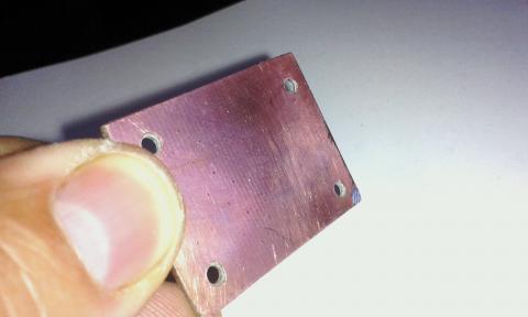
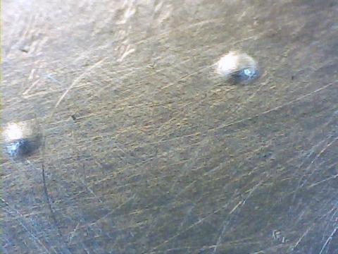
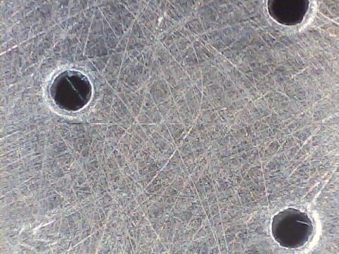
During the last weeks we have been researching on how to improve the process of making vias through-hole with TwinTeeth.

There are several commercial products for making PCB vias at home. Some based on small rivets, others on conductive epoxy. You can also use electroplating, which is the method used at the industry. In addition you can use the traditional system which consists of introducing a small wire in each via, solder it at both sides of the PCB, and cut it. For example, if you have 100 vias in your PCB, you have to solder 200 times. This can be time-consuming, but is also boring, absurd, produce a melancholic state of mind and is prone to failures.

None of these methods convince us, and we are sure that there is an alternative way for making vias at home with the help of a robot like TwinTeeth.

Main problem when looking for an alternative method for soldering or electroplating vias is the conductivity of the material. For that reason silver in frequently used in the compounds, but at a cost. Graphene seems coming to replace silver but at the moment of writing this article it is not cheap.

We started researching on it and on how to make conductive ink with graphene oxide but the price of the samples were too expensive for our taste. The idea is to make ink or conductive paste for filling the vias, andif we are going to make conductive ink, we could paint circuits as well, which is the second goal of this project.

We firmly believe in additives methods to make circuits at home and also make them in 3D. It seems that at this stage of technological development we should already have something at the DIY level, but it is not so obvious.

Behind the graphene story and exorbitant prices, we turn to the silver which is the following actor in the conductivity list. Latest researching on reactive silver inks is promising and seems to give good results. Most are based on this paper: "Reactive Silver Inks for Patterning High-Conductivity Features at Mild Temperatures" - S. Brett Walker and Jennifer A. Lewis

Here you can see a video about how to brew it at home: "Make conductive silver ink".

It does not seem complicate, although the silver nitrate needed to make the acetate cost about €50 per 25 grams and probably we will obtain only a few ml after the process. Despite it is quite reactive, it still requires an 85-100°C annealing. In other words: it does not cure at room temperature.

However there are some start-ups that found similar formulations that cure at room temperature and are manufacturing and selling them and also markers. For example this one: http://www.electroninks.com/.

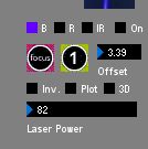
We could use these silver-ink markers on Twinteeth very easily. It is so simple as installing one on the Plotting Toolhead and paint the circuits with it.

Returning to the via topic, in the ranking of conductivity and behind silver we only found copper, so we focus our researching on this material and how to make ink or paste using copper nanoparticles.

Searching on the internet we found some videos of Robert Murray-Smith and his experiments with conductive ink. It has many and instructional videos about how to make conductive ink of different types. The most interesting for us was this one:  Homemade copper conductive paint / ink. You can see at the video that the procedure is quite simple, uses affordable materials and it seems not-too dangerous.

Before continuing, we should clarify that we only have basic skills on chemistry. The little we learned was when we where kids using a Cheminova toy and later at high-school. But Internet is a fantastic way to expand knowledge and if you have a basic level for understanding what you are reading you can learn many things.

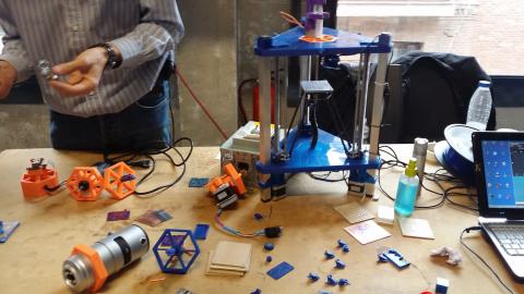
So we bought 1kg of copper sulphate and 1Kg of ascorbic acid (in total we spent about €25) and we started to brew copper nanoparticles at our garage. Acid ascorbic, despite the name, is not so acid: it is simple vitamin-C.

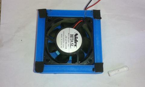
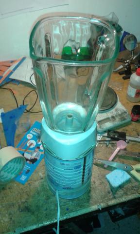
We quickly adapted an old burnt-blender to make the mixes. We used a tin of baby milk powder to accommodate the motor. We call it the "LactoMix" in homage to the Thermomix©.

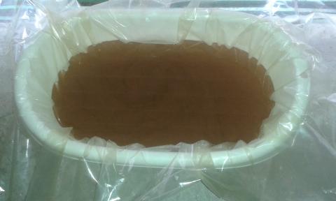
But we just got less than a gram.

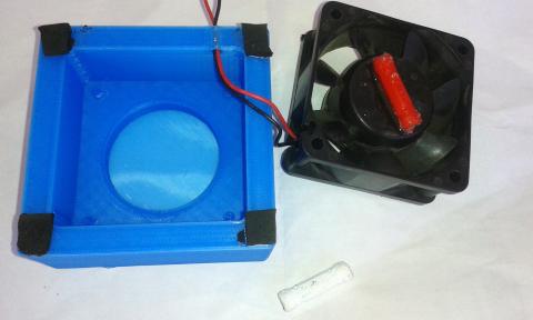
We even tried using an ultrasonic capsule to see if we improved production, but no way.

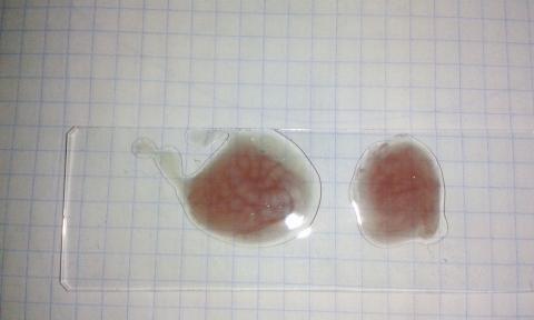
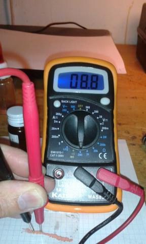
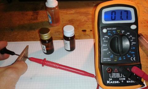
The resistivity of the final product is about 2-3Ohm per cm. We believe that it could be acceptable, at least for making vias.

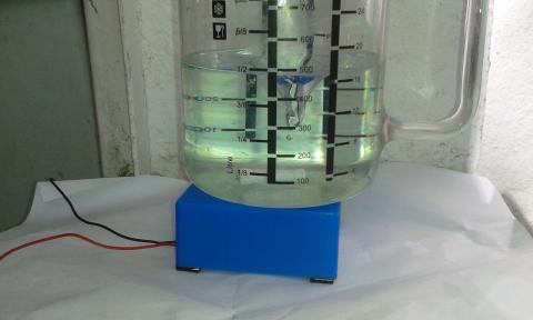
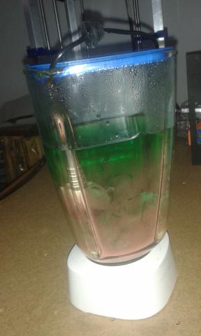
We tried brewing 20 litters in a bigger container, just to pay off the Vitamin-C investment and see what happens.

And after mining the solution we just got a few milliliters more. Not too much really. Finally we put the result into an empty Apiretal bottle and kept it in the safe box. :-)

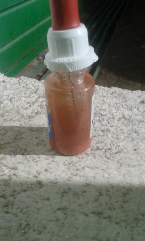
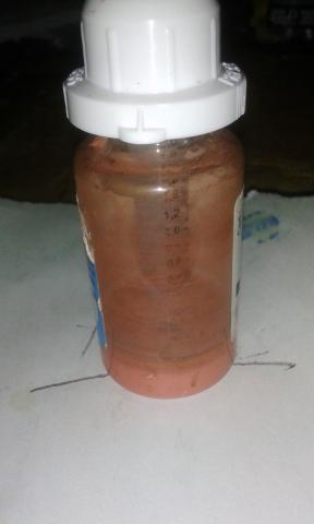
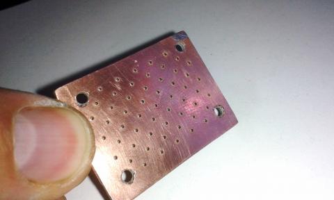
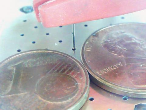
We are going to use it for "nano-testing".

Although production is easy and cheap, the method is not very productive so it does not meet our requirements.

We need a productive and cheap source of high-conductivity copper nanoparticles. We found it on the market but at “laboratory prices” aka prohibitive. In addition, the copper oxidizes very quickly and is difficult to find it in its pure form, since usually it is already covered by a thin film of copper oxide.

Interestingly, the copper oxide is cheap and we found it on ebay. It costs about €30 per Kg, but it is a poor conductor of electricity. Probably for this reason is so cheap.

Reading some publications on copper nanoparticles we discovered that there are ways to convert it into metallic copper (Cu) using a reduction reaction. It is a kind of reaction which the oxide loses the oxygen. This process is just the opposite of oxidation and is what we need if we want to use copper oxide.

To force the reduction we have to add energy and it can be done through heat (annealing), through chemical combination with other compounds, by light-flashing (using a powerful halogen lamp), by laser, and finally using some combinations of all of them.

It can be combined with hydrogen, carbon monoxide and nitrogen with the following results.

CuO H2 → Cu H2O

CuO CO → Cu CO2

CuO N2 → Cu N2O2

But the method we like is using the laser. We know a little about lasers and we have easy access to laser diodes. In addition, laser is a selective way of inducing the reaction. Perhaps we can make some kind of Cu oxide reactive paste sensible to UV light.

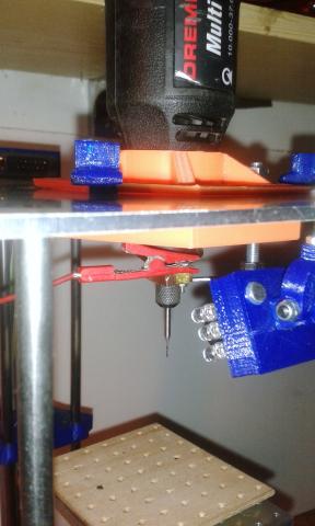
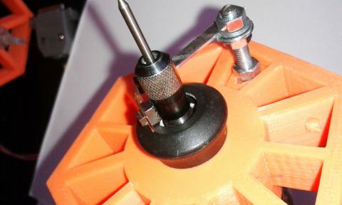
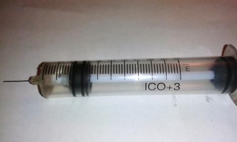
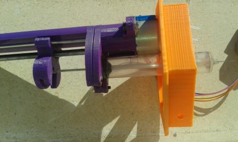
We could apply it with the Paste Dispenser ToolHead into the vias and then force the reaction with the laser and convert the oxide copper in metallic copper. Another option would be to use the IR laser and induce the reduction through heat. And another one, use a small cover on the via to inject some drops of liquid nitrogen and then hit the via with the laser on a N2 atmosphere.  

Any of them has some kind of viability on a DIY environment and meets the criteria of cost.

So, we order 100gr of copper oxide (II) to test.

While we wait to receive it we must learn more about alchemy and spend the copper nanoparticles that we already brewed.

Anyway, I think we need some chemistry technical advice.

If any of you is chemist or is studying chemistry, has some knowledge about this topic and are interested on it please, contact us. Sure we can collaborate and make something useful for the DIY community.

  • Read more about Vias, Conductive ink and Copper nanoparticles
  • Log in or register to post comments

September summary

Submitted by DIYouware on Sun, 10/04/2015 - 13:52

We did not find a moment to write new blog entries, but yesterday John Ferguson from the UK sent us some .STL files with improvements on the TwinTeeth plastic parts and we decided to sit down, write these lines, publish here the files and thank John for his excellent work and for his contribution to the project.

During September we have been really busy with the shop and making kits. After the summer vacation we had a lot of pending orders and we served them during September. 

We changed a little the kit configuration we are selling. We are using now a blue-light colour for the plastic instead the navy-blue which we were using before the summer. This colour has a big demand on the 3D printing market and frequently occurs that it is difficult to find because it’s sold-out. We changed to light-blue which is easy to find. We also included by default the aluminum platform kit in the Framework Hardware Kit because our provider had time during the summer to make some kits and now we have stock. We hope to control the demand. We also found time to improve the linear motion system and the kits include now the new lead-screws and supports (see blog entry).

On the other hand we abandoned the project of making a SLA Toolhead. We successfully tested the PHR-803T pickup and the driver to cure UV resin, but we did not see any advantage using an inverted delta robot. Probably a traditional cartesian robot will do a better job but beginning a new design would divert us from our goal, so we changed the focus of our researching activities to another side: improving the way of soldering vias. We would like to do some testing with TwinTeeth and use it for soldering and testing vias because they are always a nightmare when making PCBs at home. We have got some absurd ideas. Once again they seem the best. If the idea is not absurd enough then somebody has probably done it already. At this stage of technological development we only have two opportunities: research on complex and difficult areas investing a lot of time and money or find a backdoor: something that nobody thought of because it was absurd. As you can imagine the second way is our specialty and here we are: thinking about new methods to soldering vias using a robot. We are still waiting some equipment we bought and will keep you informed as soon as possible about results.

We are also studying optics because we want to do some researching about how to sensitize dry-film using galvos, polygonal mirrors, lenses, LCoS and LCD devices and in general any other optical method rather than mechanical. When we discovered the PHR-803T we fall in love with it and with its optomechatronic system. Optics is an important area of mechatronic and we don't know too much about it, so we will try everyday to learn a little about “the dark world of the light"…I mean: "the dark side of the force” :-)

We also would like to test TwinTeeth for printing circuits using graphene. We found some experiences on the internet where people are transforming graphite oxide in graphene using a laser beam. Maher El-Kad from UCLA University did it for the first time using LightScribe. This is an old technology which uses a DVD laser to burn a cover image into the top layer of the DVD. The method he used to make graphene seems simple: he covered a plastic substrate with a graphite oxide aqueous solution, let it dry and finally he used the laser beam to transform the graphite oxide into graphene.

You can find more information here and some videos on youtube like this one.

The first problem we found in this project was the graphite oxide’s price. We though it was cheaper than graphene which actually is really expensive. But graphite oxide is not cheaper: approx. 180$ per gram. In fact it is more expensive than inkjet printer ink: the most expensive liquid in the world.

We also had time for collaborating with Mecaduino. We met Mecaduino guys last May at the Maker Faire. They gently offered to teach us how to use more metal parts in our designs and now we are talking about how to make a project together.

That's all!

We will keep you informed.

  • Read more about September summary
  • Log in or register to post comments

Control IP5 2.2.5

Submitted by DIYouware on Wed, 09/16/2015 - 10:10

Control IP5 library guys have released a new version (2.2.5) which has several changes not supported by TwinTeethMC.

We are adapting our tool to these changes. Meanwhile please download and install version  2.0.4 which is supported.

You can download it from here.

Sorry for any incovenience.

Diyouware team.


  • Read more about Control IP5 2.2.5
  • Log in or register to post comments

Lead-screw Improvement

Submitted by DIYouware on Tue, 09/01/2015 - 15:40

After some vacation days we returned revitalizazed with fresh ideas.  

One of them has been improve the mechanical precision. Actual values are fine but during the 3D printing tests using UV resin we saw that some straight lines appear a little twisted at micrometer scale.

Probably the reason is some kind of lead-screw wobble or maybe the motor couplers are too flexible or both. So we reviewed the mechanical system in order to minimize this effect. Finally we decided to reduce the size of the acme screws to reduce possible wobble and we also designed a new lead-screw top support which will hold the bearing and a bolt to adjust the motor coupler flexibility.

Really TwinTeeth don’t need so long lead-screws because almost the top half parts of them are not used. Carriages only travel approx. 140-150mm from the home position and we can reduce the lead-screw length and prevent in that way possible wobble while rotating. We thought also to reduce the size of the steel linear guides but they add stiffness to the framework and sincerely we did not see any benefit.

These modifications are easy to implement and you can reuse the important materials: lead-screws and bearings. You will need to buy only some bolts and nuts and 3D print two new parts: the top lead-screw support and its cover. They fit on the TwinTeeth bed size so if you own the 3D Printer ToolHead probably you can print them with it (before dissemble it). Otherwise we can provide you a kit with the parts and the bolts/nuts. New framework kits will include these modifications as well.

This is how the new parts look:

And next pictures show the parts assembled:


The BOM per each axis is:

  • 1x lead-screw top support part
  • 1x lead-screw top support cover part
  • 6x M3 -10mm bolts and nuts
  • 1x M3 -12mm bolts and nuts
  • 1x M4 - 30mm bolt and nut
  • Teflon tape
  • Vaseline or grease

And the tools needed:

  • M2, M3 allen keys
  • Small screwdriver
  • Metal saw
  • Metal file
  • Marker pen

How to do it?

First you have to obtain (or 3D print) the new plastic parts. Then remove the debris, elephant foot, threads, etc. Using the soldering iron insert the M3 nuts and install the M3x10mm retainer bolts for the linear axis. Don’t forget also to install a M3x12mm and its nut for the adjustment bolt in the cover part.

Then disassemble the top triangle. Remove the three F6900ZZ ball bearings from it and install them on the new lead-screw top support parts. Use some Teflon tape to fit them in their housings.

Put some Vaseline or grease on the adjustment bolt tip (M3x12mm) of the top cover part. It will reduce the friction with the lead-screw.

Using four M3x10mm bolts, install the top cover part on the lead-screw top support part. It will retain the ball bearing.

Remove the half-nuts from the carriages. Loosen the motor coupler grub screws and remove the lead-screws.

Using a metal saw cut the lead-screws to 200mm length and file the ends.

For each axis:

Take the lead-screw top support part. Check that the linear guide retainer bolts are loosen. Slide down the part on the aluminium tube & linear guides till it will be approx. 147mm from the bottom triangle surface (measured from the bottom side of the part).

Using a marker pen, mark the M4 bolt position on the alu. tube. Remove the plastic part and using a 3 or 3.5mm drill bit, drill a hole through the tube. Warning: take care when drilling the Z tube because the wiring probably is already inside.

Loosen the motor coupler grub screws. Provisionally install the lead-screw through the carriage nut, bottom triangle bearing till it reaches the motor coupler. Then slide the lead-screw top part through the alu. tube and attach it to the tube using the M4 screw. Tighten also the linear guide retainers.

Turn the lead-screw by hand and insert it into the top part bearing until it will touch the adjustment screw. Then using a small screwdriver slide the motor coupler up till it will be pressuring against the lead-screw bottom end. Then tighten the grub screws to maintain the motor coupler on that position. The idea is to eliminate the flexibility of the motor coupler and the vertical movement of the lead-screw. Later you will be able to adjust the gap if needed by turning the adjustment screw.

Using a marker pen, mark on the lead-screw the position of the top and bottom ball bearing. Then, loosen the motor coupler grub screws (only lead-screw side), disassemble all the set and remove the lead-screw. Apply some Teflon tape around it on the marks to reduce the gap with the bearings.

Install again the lead-screw and check that it fit well on the ball bearings. It’s very important that the lead-screw fits perfectly on them to avoid wobble. Then install the top support part again. This time you should make some pressure against the lead-screw to install it (compressing the motor coupler). Install the M4 bolt and tighten the retainers.

Attach the half-nut to the carriage and adjust the bolts.

Using your fingers check that the lead-screw turns smoothly. Move also the lead-screw vertically up and down to check there is no vertical gap. The ideal is zero lead-screw vertical movement, but if you feel the lead-screw blocks, loosen a little the adjustment screw.

Finally check that the motor couplers grub screws and retainer bolts are tighten and repeat the operation with the rest of axis.

When finish, we recommend you to level again the platform and set the tool zero positions before using TwinTeeth again.

There is no software impact using this modification. So you can use the same firmware and TwinTeethMC version you used with the long lead-screws.

We recommend you to implement this improvement because it provides additional accuracy also for printing PCBs. And if you are starting assembling TwinTeeth, don’t doubt and implement it.

If you have any doubt while asemble it don't heasitate to contact us.

You will find the new version of the blue-prints and printed parts files in the Get it section.

  • Read more about Lead-screw Improvement
  • Log in or register to post comments

Pages

  • 1
  • 2
  • 3
  • 4
  • 5
  • next ›
  • last »

(c) 2013 Diyouware.com