Printing test
Today we continue with the printing tests in rastering mode with very good results.
The process of printing in raster mode begins on Eagle CADSoft which is the tool we use to design the PCBs.
Once the board is finished then we export it to PostScript format (Device: PS in the Eagle’s CAM processor) and open it with DiyouRun V2.0.
DiyouRun has change a lot since last version and now it has a new look and feel adapted to the new robot.
On the top menu you can observe some tabs with the diferent tool names the robot supports. They can grow as we will add more tools in the future.
To print the PCB just push the print button and the robot will begin.
Raster printing works in the following way:
First DiyouRun order the robot with a g-code command to focus the laser. Then the robot moves the laser to the four corners of the printing bed, focus it on each corner and save the value obtained. With these values it generates (using linear interpolation) a matrix with an approach of the focus values for each millimeter of the PCB to print.
DiyouRun then begins to scan line by line the image of the PCB file. It converts each bitmap line to base64 format and send it thorugh the USB port in 64-byte size buffers.
The firmware of the robot receives the buffers decodes them back to binary and reconstruct the bitmap of the image line.
Then it sends orders to the engines to move it from one PCB end to the other and at the same time pulse the laser and adjust the focus lens. It makes a pass in one direction and then another in the other way.
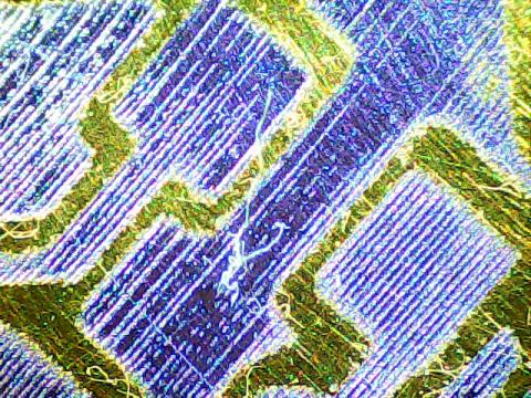
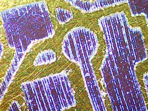
I attached some images we obtained with a microscope. The traces you can see are 17 mil wide (approx. 0.4 mm) with clearances of 10 mil (approx. 0.2 mm) and pad/vias drills of 38 mil (0.9 mm).
We think we can go beyond this values to aprox. 10/12mil for all.

The "thing" you can see in the midle of picture above is a microscopic dry-film debris.

Although you can observe the rastering lines the drawing is solid when you see it in plain sight. The changes in the colour’s tone between lines are because the printing is really in 3D (at a microscopic scale). I mean, if we were able to see it with a better microscope we will see something similar to a “ploughed field”.
I forgot to say that the robot prints now with a resolution of 600dpi. It means that each "groove" you see in the pictures is aprox. 0.04mm wide.
