Lead-screw Improvement
After some vacation days we returned revitalizazed with fresh ideas.
One of them has been improve the mechanical precision. Actual values are fine but during the 3D printing tests using UV resin we saw that some straight lines appear a little twisted at micrometer scale.
Probably the reason is some kind of lead-screw wobble or maybe the motor couplers are too flexible or both. So we reviewed the mechanical system in order to minimize this effect. Finally we decided to reduce the size of the acme screws to reduce possible wobble and we also designed a new lead-screw top support which will hold the bearing and a bolt to adjust the motor coupler flexibility.
Really TwinTeeth don’t need so long lead-screws because almost the top half parts of them are not used. Carriages only travel approx. 140-150mm from the home position and we can reduce the lead-screw length and prevent in that way possible wobble while rotating. We thought also to reduce the size of the steel linear guides but they add stiffness to the framework and sincerely we did not see any benefit.
These modifications are easy to implement and you can reuse the important materials: lead-screws and bearings. You will need to buy only some bolts and nuts and 3D print two new parts: the top lead-screw support and its cover. They fit on the TwinTeeth bed size so if you own the 3D Printer ToolHead probably you can print them with it (before dissemble it). Otherwise we can provide you a kit with the parts and the bolts/nuts. New framework kits will include these modifications as well.
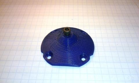
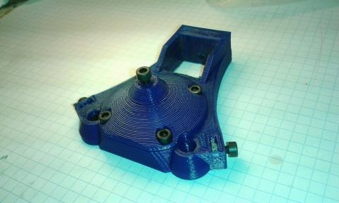
This is how the new parts look:


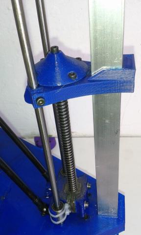
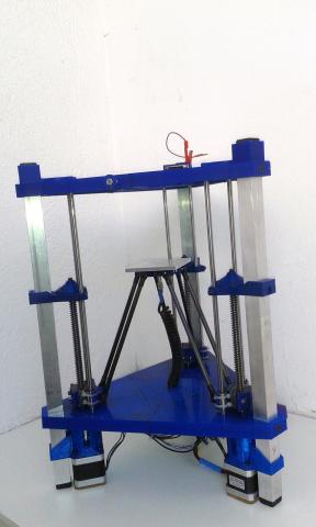
And next pictures show the parts assembled:


The BOM per each axis is:
- 1x lead-screw top support part
- 1x lead-screw top support cover part
- 6x M3 -10mm bolts and nuts
- 1x M3 -12mm bolts and nuts
- 1x M4 - 30mm bolt and nut
- Teflon tape
- Vaseline or grease
And the tools needed:
- M2, M3 allen keys
- Small screwdriver
- Metal saw
- Metal file
- Marker pen
How to do it?
First you have to obtain (or 3D print) the new plastic parts. Then remove the debris, elephant foot, threads, etc. Using the soldering iron insert the M3 nuts and install the M3x10mm retainer bolts for the linear axis. Don’t forget also to install a M3x12mm and its nut for the adjustment bolt in the cover part.
Then disassemble the top triangle. Remove the three F6900ZZ ball bearings from it and install them on the new lead-screw top support parts. Use some Teflon tape to fit them in their housings.
Put some Vaseline or grease on the adjustment bolt tip (M3x12mm) of the top cover part. It will reduce the friction with the lead-screw.
Using four M3x10mm bolts, install the top cover part on the lead-screw top support part. It will retain the ball bearing.
Remove the half-nuts from the carriages. Loosen the motor coupler grub screws and remove the lead-screws.
Using a metal saw cut the lead-screws to 200mm length and file the ends.
For each axis:
Take the lead-screw top support part. Check that the linear guide retainer bolts are loosen. Slide down the part on the aluminium tube & linear guides till it will be approx. 147mm from the bottom triangle surface (measured from the bottom side of the part).
Using a marker pen, mark the M4 bolt position on the alu. tube. Remove the plastic part and using a 3 or 3.5mm drill bit, drill a hole through the tube. Warning: take care when drilling the Z tube because the wiring probably is already inside.
Loosen the motor coupler grub screws. Provisionally install the lead-screw through the carriage nut, bottom triangle bearing till it reaches the motor coupler. Then slide the lead-screw top part through the alu. tube and attach it to the tube using the M4 screw. Tighten also the linear guide retainers.
Turn the lead-screw by hand and insert it into the top part bearing until it will touch the adjustment screw. Then using a small screwdriver slide the motor coupler up till it will be pressuring against the lead-screw bottom end. Then tighten the grub screws to maintain the motor coupler on that position. The idea is to eliminate the flexibility of the motor coupler and the vertical movement of the lead-screw. Later you will be able to adjust the gap if needed by turning the adjustment screw.
Using a marker pen, mark on the lead-screw the position of the top and bottom ball bearing. Then, loosen the motor coupler grub screws (only lead-screw side), disassemble all the set and remove the lead-screw. Apply some Teflon tape around it on the marks to reduce the gap with the bearings.
Install again the lead-screw and check that it fit well on the ball bearings. It’s very important that the lead-screw fits perfectly on them to avoid wobble. Then install the top support part again. This time you should make some pressure against the lead-screw to install it (compressing the motor coupler). Install the M4 bolt and tighten the retainers.
Attach the half-nut to the carriage and adjust the bolts.
Using your fingers check that the lead-screw turns smoothly. Move also the lead-screw vertically up and down to check there is no vertical gap. The ideal is zero lead-screw vertical movement, but if you feel the lead-screw blocks, loosen a little the adjustment screw.
Finally check that the motor couplers grub screws and retainer bolts are tighten and repeat the operation with the rest of axis.
When finish, we recommend you to level again the platform and set the tool zero positions before using TwinTeeth again.
There is no software impact using this modification. So you can use the same firmware and TwinTeethMC version you used with the long lead-screws.
We recommend you to implement this improvement because it provides additional accuracy also for printing PCBs. And if you are starting assembling TwinTeeth, don’t doubt and implement it.
If you have any doubt while asemble it don't heasitate to contact us.
You will find the new version of the blue-prints and printed parts files in the Get it section.
