Drilling vias and holes
In this chapter we will cover the process of drilling vias and holes using the Drilling ToolHead and a Dremel 200 rotary tool.
The process consists on the following steps:
- Generate the CAM files
- Install the Drilling Toolhead
- Set the program zero
- Drill the board
We will use as an example the schematic and Eagle board design we used for photoengraving the PCB with the Laser Toolhead.
Run Eagle Cadsoft and open the LaserDriver project you create for photoengraving.
Generating the CAM files
The Drilling ToolHead use g-code as CAM file format. We developed a special Eagle's ULP to easily generate g-code files from the board design. You already installed it in previous chapters. (See Installing Eagle's ULPs for TwinTeeth section on the software Installation chapter)
You have to switch to the board view to run the ULP. Select the top layer. We will drill the board from this layer on this tutorial.
User Language Programs are executed using the Run command. Click on the icon.
A file selector will appear. Go to the directory where you installed the zip file and open twinteeth.ulp file.
You will see the TwinTeeth ULP window, similar to this:
This window has two tabs with the labels: Drill Tool and Paste Dispenser Tool. The first one contains the Drilling ToolHead configuration panel and the second one the Paste Dispenser panel. When configured, you can generate the files clicking on the "Save G-code button". Files usually are saved on the same project directory.
We will describe now how to configure the Drill Tool panel.
The drilling configuration panel has several areas: the generation area, the drill bit area, the z axis control area, the feed rate area and the hole size list.
The Generation Area allows you to choose which kind of g-code files you want to generate. You can generate top side drills, bottom side drills and also mirror the bottom side drills.
At the right you have the Drill Bits area. It allows you to configure the drill bit size list use for this board.
The ULP will generate a g-code file for each active drill bit category in the list. A max of 4 drill bit sizes is allowed. To activate or deactivate one drill bit category just check or uncheck the corresponding checkbox. At the right of the checkbox you can see three fields : the size of the bit, the min size of the hole and the max size of the hole (in mm).
The Size field allows you to configure the bit size you will use for that drill bit category. The Min and the Max fields determine the range of holes diameters which will be grouped under that drill bit size. This allows you to reduce the number of drill bits used by grouping a range of holes sizes under the same drill bit.
For instance, you can see at the example that drill bit #0 is a 2.5mm drill bit size, with a 1.5mm min. value and a 3mm max. value. It means that all the vias or holes of the board between 1.5mm and 3mm of diameter (both included) will be grouped and drilled using a 2.5mm drill bit. It's active so the ULP will generate a g-code file for this category when you click on the Save G-code button.
The Hole size list provides you important information about all the vias and holes sizes used in your design. It will help you to determine the drill bit list.
All the holes sizes in that list must be covered by an active drill bit category. Otherwise when you will try to save the g-code file you will see an error message similar like this:
In our particular example we configured three drill bit categories:
The first one is to cover the 2.5mm holes of the PCB corners. We are not going to use it because they were already drilled but we need to define the category to avoid the error we mentioned above.
As you can see on the Hole Size List there are some holes of approx. 1mm. We will cover these holes with a 1mm drill bit defined at the #1 category.
You can also see at the hole list that the rest of holes has a size of 0.6mm. These are the vias. We prefer to use a 0.3mm drill bit instead of a 0.6mm, so we configured the drill bit category #2 to cover all holes in a range from 0 to 0.9mm with a 0.3mm drill bit.
Category #3 is deactivated so no file will be generated.
The Z axis control area allows you to manage the behaviour of the Z axis. You will see there the following fields:
- Z High - The highest Z axis position in mm when starting to drill.
- Z up - The Z axis position in mm when moving from one drilling to the next.
- Z down - The Z axis position in mm when the drill bit is touching the PCB.
- Drill Depth - As its name indicates it is the drilling depth in mm.
- Drill Dwell - It is the time in ms that the robot will pause when the drill bit is at the lowest position.
Finally the feed rate area allows you to set the X,Y and Z axis feed rates in mm/min.
Now check the list of holes of your board and configure the drill bit size list and the rest of parameters as you want. Then click the Save g-code button.
The ULP will generate a g-code file for each drill bit category. CNC machines frequently use only one file for all the drilling but we thought it is difficult to pause the robot, change the drill bit, calibrate it again, etc. using the same g-code file. Instead of that we preferred to separate the drilling task in several files and allows you to use it in a more flexible way.
The name of the files generated will be similar to these ones:
- twinteeth-laserdriver.brd.drill.top.#0.gcode
- twinteeth-laserdriver.brd.drill.top.#1.gcode
- twinteeth-laserdriver.brd.drill.top.#2.gcode
You will find them at the Eagles's project directory.
The filenames have various sections: the #n is the drill bit category, the top word means it is a file for drilling from the top side and the drill world means it is a drilling file. The rest is the filename itself.
Installing the Drilling ToolHead
In this section we are going to prepare and install the Drilling ToolHead.
Find the Dremel tool and the bits. Install the tool on the hexagon as we described in Assembling the Drilling ToolHead chapter.
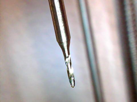
We will begin with the 0.3mm vias, so install the 0.3mm drill bit into the chuck and tighten it.
Install the ToolHead and plug the Dremel tool in.
Run the camera application and adjust the camera pointing to the drill bit. Focus the objective if needed and turn the LEDs on.
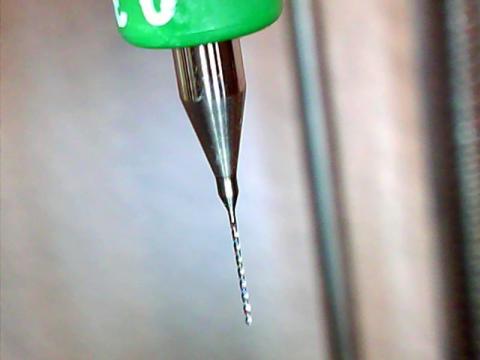
Install on the platform the sacrificed plywood board. It was optional using other ToolHeads but it is a must when drilling.
Finally install the PCB on the sacrificed board.
Warning: if your PCB does not fit well on the pins then it could fly out during drilling and hurt you. Use some strips of adhesive tape to attach it securely in place.
Check that all the drilling stuff is ready.
Setting the program zero
Run TwinTeehMC and connect with the robot.
Select the Dremel tool clicking on the tab of the ToolHead Menu.
Home the platform. Click on the Calibrate button to show the calibration controls.
Set the Z min slider to the thickness of the PCB plus a little bit because drill bits usually have a round end.
Click on the Reset tool button to initialize the tool configuration and click on Home again.
Then using the Z control move the platform up till the drill bit almost touches the PCB surface. Then move the X and Y axis till the drill bit point to the circle you draw at the Eagle's board design. After the etching process the circle is a small isolated rounded pad on the cooper foil. That is the center of the board and you have to set it as the coordinate origin.
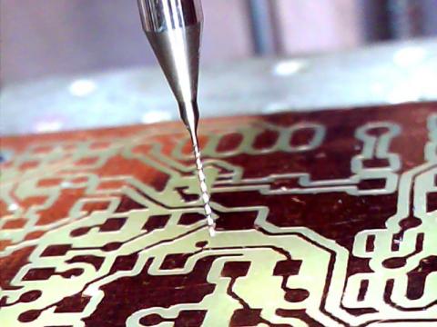
Carefully move the Z axis till the drill bit touches the PCB surface on the center pad.
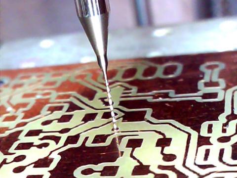
Then click on the Set Program Zero button to set the current location as the coordinate origin.
Click again on the Calibrate button to hide the calibration controls and home the platform.
To check that it is well calibrated click on the "Goto Zero" button to go to that position. The platform will move up and stop just when the drill bit touches the PCB surface.
The Drilling ToolHead is ready.
Drilling the board
In this section we will run the job.
As we already installed the 0.3mm drill bit on the tool we will begin with the corresponding g-code file.
Click on the Load File button and load it. You will see a representation of the tool path at the Simulation Area. Each line corresponds to a platform movement and the circles to the drilling.
As you probably saw, there is only one auxiliary control on the Dremel screen called Peck Test. If you check on it, the Z axis will not go beyond the zero location (when the program is running). It means that it will not drill the board: just touch it a little bit. This functionality is very useful to test if the program zero position was correctly set.
So activate the Peck test checkbox to run a test. Then click on the Run button.
You will see how the platform goes home and then moves up following the tool path loaded. It will peck the drill bit at the drilling positions, usually pads or GND areas.
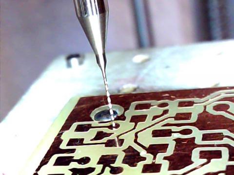
Check using the camera view that the drill bit is centered on the pads. If not you should go back and adjust the zero position slightly.
If the testing was suscesful, uncheck the Peck Test checkbox, turn on the Dremel, select the appropriate rotation speed on it, and click again on the Run Button.
The robot will start to drill the PCB.
You will see the evolution of the job at the simulation area and through the camera.
When the job is finish, turn off the Dremel, home the platform, change the drill bit and run the next job file.
You will need to set again the zero position because it's almost impossible to install the new drill bit exactly at the same length that the old one.
When finish, remove the board from the platform and using fine grade sandpaper sand it a little to remove drilling debris.
The board is drilled!

We will see in next chapter how to dispense solder paste on the pads.
Previous chapter Use it Index Home Next chapter
