Hacking the PHR-803T
One day we were playing with a Xbox blu-ray sled trying to turn the laser on and we thought: could the blu-ray laser be used to print circuit boards?. The sled has a UV laser diode and maybe we can sensitize Dry-Film or presensitized boards with it.
Eight months later we did it using the famous Toshiba PHR-803T blu-ray pick-up.
Well, really it's HD-DVD not blu-ray, but they are similar technologies. It is very popular because It was spread around the planet inside the Xbox 360 DVD player.
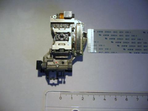
The idea of using a blu-ray laser diode is not very original; we found similar experiences on the Internet, all of them based on removing the diode from the pickup and installing it on a CNC machine, a laser printer or a 3D printer.
But we didn't want to tier down the PHR-803T because it is a jewel of engineering. We also hate to destroy things: we are makers not destroyers, although finally we broke some of them to learn how they work.:-(
In addition, we wanted something as simple as buying the pickup and connect it. fortunately the lack of PHR-803T technical information forced us to hacking it. :-) And using reverse engineering we figured out the connector pinout and took advantage of the complete system: auto-focus, lens up and down, laser power, laser oscillator, etc, all through it's own electronics.
We started the project on February 2013 but break on several times thinking that it was not feasible. Finally, on October 2013, we did all tests successfully. In total it was about 8 months of work.
On March 2014 we re-designed the circuitry in order to improve it, and in October, 2014 we finally made the actual Pickup Driver version 3.3 which can control and focus with the three laser diodes, among other improvements.
DiyouPCB
We wanted to use the PHR-803T to build a PCB printer. Something similar to scanners or photocopiers: just open the door put the copper board on top of the window, closes the door and presses the print button. We called it DiyouPCB
But unfortunately the mechanics and timing belts produced mechanical vibrations affecting the laser beam. The beam spot is so tiny (some micrometers) that any small vibration affect it. We fought some months with the vibrations and finally we lost: it was almost impossible to eliminate them.
TwinTeeth
So we started again from scratch with new designing criteria: reduce vibrations and resonances. To avoid them we used Acme screws instead of belts and we decided to move the PCB instead the laser. DiyouPCB is based on a traditional cartesian robot design using timing belts so this time we will try something different: an inverted delta robot.
At the same time we wanted a tool very easy-to-use because make PCBs at home is a tedious task. The complete process includes managing diverse techniques: printing, etching, drilling, dispensing, placing components, soldering, etc.
This is the ideal environment for a multi-functional robot. We though that interchange the tools had to be very easy and fast. Otherwise nobody will want to use it frequently. Also we though in the future: there are people around the world researching about printing circuits with conductive ink, filament, graphene, etc. This is the next evolution of electronics: 3D printing circuits. So, we also added a 3D extruder and the possibility to extend the robot with more toolheads.
TwinTeeth was born: a multi-functional robot to make PCBs at home. It also uses the PHR-803T but with an improved electronic driver.
The PHR-803T
The PHR-803T incorporates a UV laser diode on the 405nm wavelength. The spectrum and power is more than enough to sensitize UV film even resin, but we couldn’t find any technical information about it. We sent several e-mails to the manufacturer without success. After searching all the web we decided to open and analyze some of them.
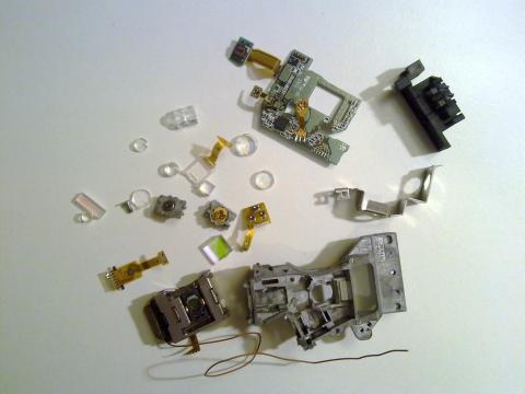
The PHR-803T is a masterpiece of engineering manufactured by Toshiba. Nowadays, optical storage technology has been largely superseded by other technologies like flash memories. In fact Toshiba has discontinued HD-DVD readers/writers so there are in the market many spare parts at low prices.
The pickup incorporates some interesting components:
- Three laser diodes: UV 405nm (HD-DVD), Red 650nm (DVD) and IR 780nm (CD)
- A focus lens and coil servos for auto-focus, tracking and correction angle.
- A photodiode array which receive the RF signal and help focusing on.
We learned a lot about lasers at the page of Sam (Sam's Laser FAQ ) and got the little information available about the PHR-803T. Sam include in his web a very interesting photo of a exploded view that helped us to identify its components.
If we see the picture on Sam's page, the laser operation is relatively simple:
- The laser diode (2) emits UV light that is conducted through a system of mirrors and prisms until the focus lens (12).
- This lens can be moved in several axis using three coils. This allows the pickup to focus the laser on the disk, follow the audio track (tracking) and correct the laser angle.
- Once the laser is reflected on the disc surface, it goes back through the lens (12) and through more prisms and mirrors is redirected toward the photodiode array (4) where we get the RF signal as well as the signals needed to correct the focus and align the laser with the track (tracking).
- To auto-focus, the electronic reader reads the signal from the photodiodes (4) and moves the focus lens (12).
All the information about optical pickups is often classified. It is possible to obtain only superficial information about old models of CD or DVD readers. Thanks to them we began to learn about optical pickups and got very valuable information to deduce how use the PHR-803T. After all, the DVD technology was an improvement on the CD, and the HD-DVD/Blu-Ray an improvement on DVD, so we thought that the techniques used should be similar and the pinouts similar as well.
For our purposes we just needed to turn-on the laser, modulate his power and focus it properly on the PCB. The PHR-803T has a FPC connector of 0.5 pitch with a 45 pinout. Only connect some wires to the connector took us some time. We finally designed a special breakoutboard to easily "sniff" the signals.
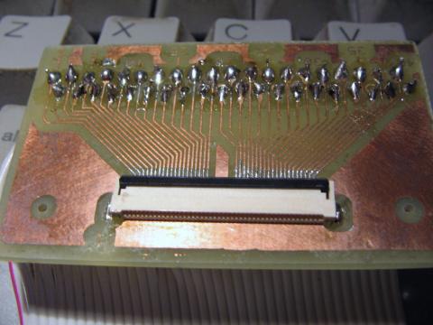
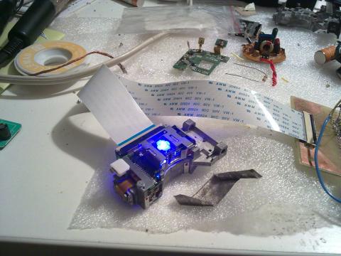
We followed the traces on the flexible PCB to deduced some pins. The more obvious were the traces from the connector to the lens coils. We found also the pins of GND and VCC which are several (2.5V, 5V and 9V).
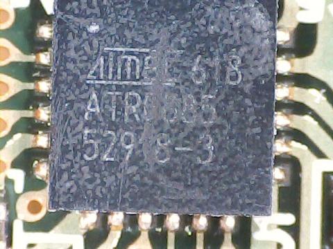
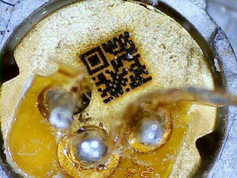
Under the microscope we saw that the pickup uses a chip: the ATMEL/ATR0885 and we found on the Internet its Datasheet. It is the HF driver that manages the laser diodes. We got also the datasheet of the 405nm laser diode. We are not sure, but we believe it's the Sharp GH04P21A2GE. Curiously, the laser diode has a tiny QR code, but we couldn't read it.
Burning some pickups we conducted some tests and finally we figured out the pins we were interested on: 405nm laser on/off and current control, the VCC pins and four photodiodes signals, called in almost all pickups tech. references A,B,C,D signals. Adding and subtracting these signals the DVD reader conforms the called Focus Error (FE) signal, which tells the reader if the laser is focused. We think that we also know the pins of the RF signal but we have not investigated enough. Anyway we do not need it to build the printer.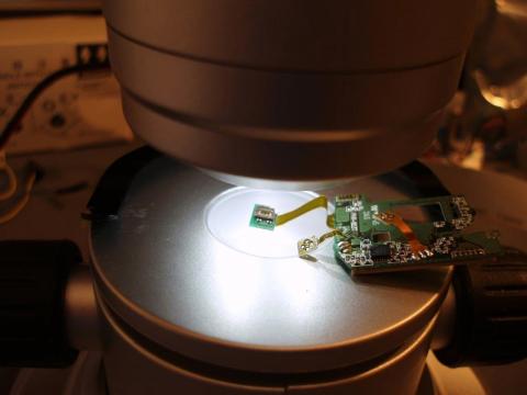
The Pickup Driver circuit
Once we found out the pins, we designed the circuit to control it: turn on/off the laser, control the intensity, move the focus lens, read the photodiodes signals and be able to perform auto-focus.
We call it the Pickup Driver.

The Pickup Driver V1.0 circuit.
More complex was to obtain the Focus Error signal (FE) since the original DVD readers implement complex electronics that focus the laser on the disk in real time. Play with it was completely out of the scope of our project, so we though we can did something simpler because we didn't need to focus the laser continuously on the PCB.
We only needed to focus the laser at the beginning of printing, but of course not directly on the board, because we risk sensitizing the dry-film during the focus process. Finally we decided to use some type of reflective material in one of the printer's corner that would be at the same pickup distance than the PCB and where the laser could focus before printing. We did it with a square of 10mmx10mm of alu. foil and it worked!

The first Pickup Driver prototype
First testing
We thought could be a good idea to install the pickup in our 3D RepRap printer, replacing the extruder. We put below a PCB covered with dry-film and we conducted some tests.
When we developed the film we saw that the idea could be feasible, but there was a lot to improve.

Auto-focus: the astigmatic method
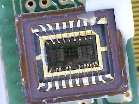
Optical pickups focus on disc using the so called astigmatic method. This method is based on the deformation of the roundness of the laser beam when it is unfocused. The pickup has a series of lenses that lead the reflected ray to a photodiode array which generates four signals (A,B,C,D). Using them it is possible to deduct if the laser is unfocused and move the lens to focus it correctly.
The photodiode array
Once you know the A,B,C,D signal pins, implementing the auto-focus algorithm is easy: just add A+C and subtract B+D from the result. The pickup returns those signals in the form of minimum current variations that depend on the laser light received by each photodiode. The photodiodes are arranged in a square (see following figure).
As you can see, it is possible to infer the focus level checking if the result is less than 0 (too close) equal to zero (focused) or greater than zero (too far) and with this information move the lens until the laser is focused.

It seems easy so we bought some high-speed op-amp (TLC2274C) to amplify and combine the signals and obtain one that we could interpret in an Arduino analogue port.
Tunning
After some testing we began to have an idea of the laser power needed to sensitize the dry-film.
It depended on the printing speed and power. Too much power at low speed and the laser overexposed tracks surroundings. Less power or high sped and the laser didn't sensitize enough the photoresist. All these tests we did were focusing manually, by moving the Z-axis of the RepRap 3D printer up and down. Although the Pickup Driver was generating the FE signal, we had not yet developed the Arduino's software that would read the signals from the photodiodes, so we run manually.
Right away we saw an additional difficulty: the laser power needed to sensitize the dry-film generated an excess of light (halo) surrounding the main laser beam and exposing the tracks surroundings. There was no way to fix it. If we reduced laser power the halo disappears but we couldn't sensitize the dry-film. We were close of abandoning the project.

First blurred testing
Solar Film: the solution
We have no idea of optics and we didn't want to modify the pickup, nor of course change their lenses.
Inspired on a sunny day, we though we would install sunglasses on the pickup and filter out the excess of light.
We tried with some kind of sunglasses and it works, but how would install them in the pickup and at the correct distance? In addition sunglasses are expensive and this solution broke several of our design rules: low-cost, not tier-down, easy to do, etc. Finally, we found a better solution: solar film.
Solar film is this kind of sun protective film used in home and car windows to filter UV light. It is very cheap and it's sold with different degrees of UV filtering so we tried with one semi-transparent (mirror-style) and it worked.
The film is self-adhesive and we simply pasted it on the printer bed glass. It is cheap and meets all the requirements. It also protects the PCB from ambient light.

First decent printing
Actually we paste the solar film directly on the PCB, but probably it is possible to use other methods: glue it on a thin glass or just paint the glass with blue paint which filter some UV light.
The auto-focus algorithm and the S-Curve
At this stage we could sensitize the dry-film with good quality but still focusing manually so we boarded the development of the auto-focus algorithm.
The Pickup Driver circuit performs the operation ((A+B) - (C+D)), generating a Focus Error signal. Our goal was read that signal, interpret it and move the lens to the appropriate focus point. But, once more time, it won't be so simple.
While sniffing the FE signal with the oscilloscope we saw a lot of back noise. We try moving a DVD disc in front of the pickup and we appreciated (once in a while) a very fast sinusoid wave. At that moment we didn't know it was the famous S-curve. For some reason that we unknown, the photodiode array get excited only when there is a variation on the disk distance. In other words: we must move the pickup lens up and down to trigger the wave.
Reading some CD's manuals we understood how it works.

The algorithm is as follows:
- Turn on the laser. (Note that if the laser power exceeds a certain threshold the photodiode got saturate).
- Move the pickup lens bottom and them up to determine the amplitude of the S-curve (and also detect if there is a disc or not).
- If there is no disc, generate an error. (In our case if there is no reflective material or if it is far away from the pickup).
- Immediately move the lens up and down while monitoring the signal.
- If the signal is equal to the amplitude divided by 16 the laser is focused (in our case we have set this threshold at 48 because we don't neeed such precision, in fact focus too much produces a laser beam below 0.1mm wide and this is a problem more than a solution).
To implement this algorithm in the Arduino, we filter the back noise and sample the signal with an analogue port. Then we analyze the signal in real time, while we moved the lens up and down with another thread, until we detect the S-Curve and found the focus point.
The method is not 100% reliable and has some margin of error.
Probably we can not read DVD disks with it, but we can use it to print PCBs with a very good precision. We empirically measured the laser beam spot and it is approx. 0.04 wide when is focused.
Good enough to print PCBs!
Pickup Driver V3.3 the evolution
Main problems we had with Pickup Driver first prototypes were produced by electric noise.
The FE signal we obtain from the pickup with the S-curve is very sensitive to that noise and it's difficult to find the focus point if the curve is hide into it.
When we developed TwinTeeth, we re-designed the circuit and we put on the same PCB some components which were isolated before: some in the own driver and some in the Arduino UNO shield. We migrated from UNO to Arduino Mega and Ramps so we did not need the Arduino UNO shield any more. But in the new circuit the focus lens Mosfet driver were in the same PCB that the rest of circuitry. This driver generated a lot of electric noise because is controlled by PWM. And the worst: it inducted the noise in the FE signal we use to detect the S-Curve and focus the laser.
So we re-designed again the circuit in order to split it in two parts and isolated digital and analogue circuits on different PCB areas. Also we used different GND and VCC lines connected in a star configuration to a common point, and we reduced PWM traces length ad minimum. Also we isolated connector pins and decouple everything with some tantalum capacitors which are more suitable to the range of frequencies we were treating. We also included a choke to filter well the power suply noisy frequencies.
We made and tested the new circuit and it worked fine, even better than the DiyouPCB prototype.
The isolation of the analogue and digital circuits produced a free-of-noise FE signal which allow us to focus fine and which more accuracy than in previous versions.
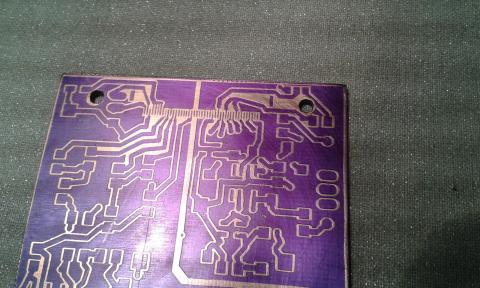
Then we ordered some PCBs to a professional manufacturer because we wanted to test if the circuit still works while reducing traces, clearances, vias and sizing. Usually the quality of this kind of services is far away from the quality we can obtain at home.
This PCB and circuit is the last version we are using (V3.3) and it works really well.
Improving the focusing system
When we developed TwinTeeth we wanted to seize the opportunity and improve the focusing system we had used for DiyouPCB.
DiyouPCB used the UV laser diode to focus in one corner of the printer where we put some reflective foil. But we saw during testing that it was not enough robust because small variations on the PCB surface could affect the laser focusing.
TwinTeeth uses a smaller printing platform than DiyouPCB, so the first idea was to focus the laser on four reflecting focus points glued under a glass over the PCB. The robot automatically moved the toolhead to those focus points and took four focus measures. Then it used them to extrapolate the data to the rest of the PCB so it can accurately focus the laser while rastering the PCB picture. But we had some problems with the glass thickness. We were using an inadequate 2mm glass and we had to change to 1.5mm glass which worked better. But even with the new glass we were not satisfied because the focus points were too far from the PCB corners so the measures were not accurate.
If we wanted to improve the focus accuracy we had to focus on the PCB corners. This is not a problem because the PCB is reflective enough to focus directly on it but, as always happens, appeared two secondary effects: first we blurred the dry-film because the UV laser sensitizes it on the places it focused; second we had to focus through the glass and the solar film. Remember that we use the solar film to filter the UV rays and protect the PCB from the “halo” effect produced by the pickup lens. The filter was good while we printing but diminish performance when we focusing. So we were again in a dead-end alley.
The solution we found was to use the red laser.
The PHR-803T is fantastic. It has three laser diodes: one in the infrared band for reading CDs, one on the red band for DVDs and one on the near UV band for HD-DVD/Blu-ray. When we developed the first prototypes we didn’t paid too much effort on the red lasers because we were focused on sensitize the dry-film with UV light.
Use the red laser to focus had some benefits:
- We could focus on the PCB corners which are the best method.
- Red laser did not blur the dry-film because the red light doesn’t sensitize the film.
- We could see the red beam better than the UV beam so additionally we can use it as a laser pointer to calibrate the robot.
- Solar film doesn’t filter red light, just UV light, so we can focus through the film.
- And... if we can focus through the film may be we can remove the glass.
The reason why we use the glass when using the laser toolhead is really because we need to glue this film on something. We “opened” some windows in the corners of the film to install the focus points, so the film doesn’t filter the UV.
So we modified the Pickup Driver PCB to control the red laser.
It was easy to turn the red laser on but unfortunately the red diode needs less current than the blue and when we turned it on it auto-destroyed. It happened three times till we deducted the problem, so we killed three more pickups during this testing. Finally we limited the current of the red laser diode with a resistor.
But once again we were not lucky enough: the S-curve we observed at the oscilloscope was very small. So we were decreasing the resistor in order to increase the current and obtain better S-Curve amplitude. But at some level the diode destroyed itself again. So, we think probably the red diode and its electronics provides a lower gain than the blue one and we should amplify it more if we want to obtain a usable S-Curve, because it’s not possible to increase the luminosity of the diode without destroyed it.
We were almost to throw in the towel when we did a quick test with the infrared diode. We had a few pickups with the red diode burned but the infrared diodes seem still alive. When we discovered the way to turn on/off the blue and red pickup’s diodes we were also able to manage the infrared one. But for some reason we didn’t see any wave in the FE signal when trying to focus with it.
Reviewing old CD/DVD player’s manuals we saw that the photodiode is usually divided into two patterns: one for DVD and another for CD. That made us though that some pickup pin had to have the function of change from one photodiode pattern to the other.
And so it was. There is a pin which allows switch from Blu-ray/DVD to CD mode. If not used this pin, infrared diode turns on but no wave is obtained while focusing. We slightly modified the driver circuit and finally we are able to focus with the infrared diode. The good news were that limiting the current with a 60Ohm resistor it seems it did not destroy itself.
We did extensive testing with this version and the printing quality was good. We took some pictures with a 20x microscope.
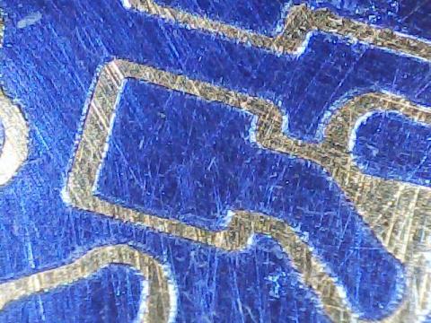
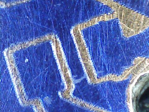
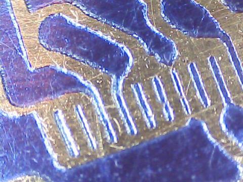
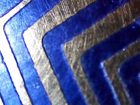
It was November 2014 when Dr. Noboyuki Futai from Japan sent us and email with the photodiode datasheet which we believe the PHR803-T uses. That document contained the last information we needed to reveal all the secrets of the PHR-803T and solved all of our doubts and confirmed some of our researches.
Actual Pickup Driver version focus with accuracy on the four corners of the PCB using the IR diode.Then it extrapolate the focus data obtained to all the PCB surface and use it to maintain the lens focused while printing. It doesn't blur the film because the IR light does not affect the film and as the laser is perfectly focused we can print circuits at 600DPI which is similar quality does commercial paper printers have.
Benefits of using a blu-ray pickup
During the project we received some emails of people asking us why so obstinacy to use a blu-ray pickup instead of a 405nm laser pointer.
The reason is because using the pickup we have a lot of benefits. It can focus automatically with precision and has a very small focal length, only of a few millimetres. This allows to print with an accuracy impossible to achieve using a laser pointer. These laser pointers have a min focal distance of approx 250mm and you have to focus them by hand without any precision and reference. Instead, the pickup slips just a few millimetres from the surface of the PCB and the auto-focus system adjusts the laser to the small variations on the platform. On the other hand a short focal length means that the pickup is more secure: not dangerous if you follows basic laser safety rules, even unenclosed. Laser pointers are really dangerous because has a poweful long-range laser.
Next steps
There is a lot of undiscovered pickup functionality yet. I hope our project had inspired some people to research more pins and end our job. For us it is enough as we covered our goals and we will continue with our project: the PCB mini-factory.
