Diyouware TwinTeeth: a PCB mini-factory
Yes. We changed the name of the project to TwinTeeth. Why? Because we did not like MKII and also because that word inspired us in the robot designing. We don’t want to bore you now with the details so we will explain the full story when we will publish the project by january/february.
We have also coined a new term: PCB mini-factory. One year ago we had the vision of a robot which would help us to fabricate small PCB prototypes at home. During its development we though some possible definitions for this concept and now we think that mini-factory is the best.
More news: we tested the “professional-made” pickup’s driver PCB and the results are fantastic!!!
The electric noise has almost disappeared and we were able to focus with the IR diode very easily and without blurring the UV-film which was our primary goal. We were also able to turn on/off the red diode but we were a little afraid about destroying it, so in addition to the limiting resistor we also limited the diode intensity by firmware.
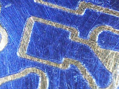
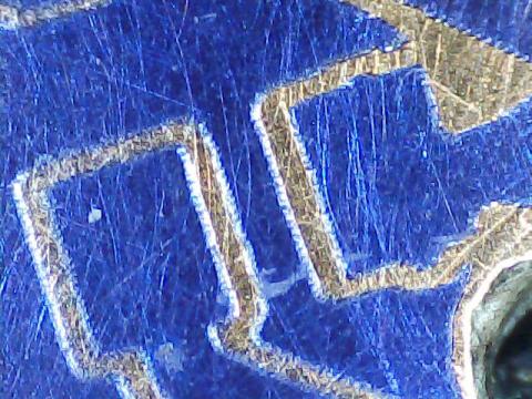
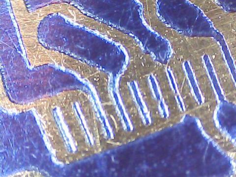
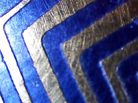
Take a look at some pics we took with a 20x microscope. They correspond to some details of the Pickup Driver PCB.


You can see on this one the 0.5mm pitch FPC connector tracks. It’s the small thing we have ever printed.

We will continue testing the printing quality but we can say that this stage has been almost surpassed.
Next stages: we have to 3D print some framework pieces we redesigned with improvements and then we will test the complete “mini-fabrication” process of a two-side PCB, including: designing, photoengraving, drilling, acid etching and dispensing solder paste on SMD pads. At the same time we will check usability and software functioning. We already tested the 3D printing toolhead but maybe we will also test it a little more. We would also like to test milling/carving on a soft material like expanded polystyrene or wax. For example it can be useful to make silicone moulds.
We hope the final functionality of the PCB mini-factory will be the following:
- Laser photoengraving – consists in drawing the PCB circuit on sensitive film or board using a UV or IR laser.
- Drilling – it allows drilling vias and holes using any mini-rotary tool like Dremel or Proxxon.
- Milling/Carving/Etching – using the same tool, it can also mill or carve soft materials or etch PCB copper with a v-bit.
- Solder paste dispensing – with a special syringe dispenser, it can deposit solder paste with precision on SMD PCBs pads.
- Plotting – if you prefer this method, you can plot the circuit with a permanent pen-maker.
- 3D printing – the mini-factory includes also a 3D printer so you can make knobs, boxes, front-panels, etc. with PLA or ABS. And also print circuits with conductive filament or graphene filament in the future!!
- And much more… because it is extendable and you can use any other tool you can install on it.
All of this functionality is supported by the robot firmware and a new user-friendly management console we have been developing this year. It will help all of us to control the mini-factory and the different tools.
We also have detected some new possible applications:
- UV resin 3D printing – we already talked about that. It is the well known Stereolithography (SLA) method. It consists in 3D printing objects with an UV laser in photo-sensible resin. We already drafted some blue-prints using the optical pickup and probably will be our next project.
- Bio-polymer 3D printing – consists in 3D printing in bio-polymers for tissue engineering. It seems easy: just add a UV photo-initiator to any hydro gel and 3D print on it with the UV laser beam. The benefit to use the pickup could be the precision because the laser beam is perfectly focused and close to the hydro gel surface. There are labs and universities around the world working on that.
- Microscopic applications – we don’t have too much time to research more areas, but we dream with this kind of projects. It consists in using the pickup as a laser microscope or molecular tweezers. In theory the laser beam is 0.5um wide so maybe is possible to do something at this scale.
Finally we promised to publish Dr. Futai’s document. Here it is:
http://www.digchip.com/datasheets/parts/datasheet/287/MLX75012.php
It is the datasheet of the photodiode array which we believe the pickup uses. This document confirms us the functionality of some of the pins we discovered last year and others we didn’t have any idea about it. It also allowed us to have a better control of the pickup’s laser diodes.
There is a lot of undiscovered pickup functionality yet. I hope our project had inspired some people to research more pins and end our job. For us it is enough as we covered our goals and we will continue with our real project: the PCB mini-factory.
Sounds good, isn't it?
