DiyouPCB – Assembling the printer framework and X-axis
In this section you will assemble the printer famework and the X-axis, but first you'll start preparing some parts that you will need later
Preparing the Printing Bed Supports
Parts required:
|
Quantity |
Material |
|
|
4 |
Printing bed supports |
|
|
8 |
M3 Nuts |
|
The printing bed is supported by four M3 bolts in these plastic parts. Before installing the suports you must insert some nuts where the bolts will be threaded.

Each support has two nuts: one in the upper side and one on the bottom. Use the soldering iron to insert them.

In the lower nuts, use a little melted plastic to hold the nut in its housing.

Assembling the X-axis belt tensioner
Parts required:
|
Quantity |
Material |
|
|
1 |
X-Axis belt tensioner plastic part |
|
|
1 |
Idle pulley shaft (6 x 20mm) |
|
|
1 |
Bronze bushing bearing 6mm(d)x10mm(D)x12mm(L) |
|
|
2 |
Drop of oil |
|
Identify the parts:

Before assembling the tensioner, clean the shaft housing of chaffs and check that you can insert the shaft into. If necessary, fix the shaft housing with the soldering iron.
Then apply a drop of oil on the shaft and another into the bronze bearing.

Insert the shaft in the bronze bearing and press both into the tensioner's housing, pushing them until the end.

Check that the pulley rotates freely and without friction.
Assembling the X-axis tensioner support
Parts required:
|
Quantity |
Material |
|
|
1 |
Assembled X-axis Belt Tensioner |
|
|
1 |
X-axis tensioner support |
|
|
2 |
15mm springs |
|
|
2 |
M3 x 20mm Socket Head Cap Screw Allen Bolts |
|
|
2 |
M3 washers |
|
|
2 |
M3 nuts |
|
Using a 6mm threaded rod check that the tensioner support hole is of the correct size. If it wasn't use a 6mm drill bit to enlarge it.

Check that the assembled tensioner fits well in the housing provided in the tensioner support.

Insert two M3 nuts in the rear of the tensioner support.
Insert two 15mm springs into the holes of the support front. If the holes were smaller than the springs, review them with a 6mm drill bit.
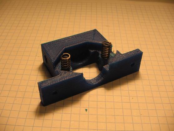
Place the tensioner into the support and thread two M3 x 20mm bolts by pressing the springs.

The support and the mounted tensioner will look like this:

Mount the X-Axis Stepper Motor
Parts required:
|
Quantity |
Material |
|
|
1 |
X-axis motor bracket |
|
|
1 |
X-axis motor support |
|
|
1 |
Nema 16 stepper motor |
|
|
1 |
T2.5 16 teeeh motor pulley |
|
|
1 |
4 pins motor connector |
|
|
4 |
M3 x 5.5mm Socket Head Cap Screw Allen Bolts |
|
|
4 |
M3 washer |
|
The X-Axis stepper motor will be attached to the X-axis motor bracket that is supported in one side by a 6mm threaded rod and a kind of triangular column (the motor support) in the other side.

Using one of the 6mm threaded rods check that the hole in the motor bracket is of the correct size. Use a 6mm drill bit to enlarge it if needed.

Put the pulley on the motor shaft. In the X-axis motor, the pulley is inserted upside down. Tighten the M2 grub screw.

Then insert the motor into its bracket and screw the motor support to the bracket with two M3 x 5.5mm bolts.

Screw the other two M3 x 5.5mm bolts that attach the motor to the bracket. Do not forget the washers.

Now is the time to install the motor connector.

The wiring diagram of the X-Axis motor is identical to the Y-axis motor:

Solder the wires to the connector in the following way:
- Green - pin 1B of the connector on the PCB.
- Black - pin 1A of the connector on the PCB.
- Red - pin 2A of the connector on the PCB.
- Blue - pin 2B of the connector on the PCB.
Assembling the Printer Framework (I)
The printer framewaork is bolted to the base of the printer and supports the x-axis with its stepper motor and idle pulley and the printing platform.
Parts required:
|
Quantity |
Material |
|
|
1 |
Printer base |
|
|
1 |
X-axis Belt Tensioner (assembled) |
|
|
1 |
X.Axis Stepper Motor (assembled in motor support) |
|
|
4 |
X-axis Shaft Supports |
|
|
2 |
Steel shafts 6mm (D) x 327mm |
|
|
2 |
M6 Threaded rods |
|
|
4 |
M3 x 19mm Socket Head Cap Screw Allen Bolts |
|
| 4 |
M3 x 17mm Socket Head Cap Screw Allen Bolts |
|
|
8 |
M3 nuts |
|
|
12 |
M6 nuts |
|
|
12 |
M6 washers |
|
First you will sand the base of shafts supports,tensioner support and X-motor support.


Then insert a threaded rod in the side hole of one of the Shaft Supports and check that it slides easily. If necessary, correct with a 6mm drill bit. The rod should NOT tap into the hole and should slide smothly but without excessive slack.

Insert also a steel shaft in the upper hole of the support and check that the hole is of the correct diameter. Remove with a cutter possible traces of printing. DO NOT use here a drill bit because you could damage the shaft housing.

Insert with the soldering iron three M3 nuts in each Shaft Support part: two in the base and one at the top. Screw an M3 bolt in the jaw that will hold the shaft. For the moment let it loose.


Choose one of the supports (which will be in the printer home position) and insert an extra M3 nut (see photo below). It will be used to screw the bumper bolt of the X-axis end-stop microswitch.

Next you will assemble the frameework of the printer.
Important: The framework must be perfectly squared otherwise the printer will not work properly and the X-axis will not slide smoothly.
Now you will mark with a pen a few reference lines on the printer base (in the drawing below in red). Later you will screw there the Shaft Supports and other pieces of the framework.

First draw a horizontal line at the top (38mm from the edge of the base). Then, using it as a reference, draw with a square ruler the vertical lines. Finally draw the bottom line at the distance shown in the figure (285mm). It is very important that all the lines form a rectangle of 90 degrees angles. To make sure everything is square you can measure the distance between opposite corners of the rectangle and check that is identical.

Now mark with a punch the intersection of the vertical lines with the reference line (the first that you draw) and drill out there two 3mm diameter holes.


Then you will screw with 2 x M3 bolts (from the underside of the base) two shaft support parts, one in each hole. Insert in their jaws one of the 6mm shafts to check the alignment.

Then make sure that each shaft support is aligned with the vertical lines and mark with a punch the hole of each support base.

Remove the shaft supports from the printer base because you will need to drill two more 3mm holes. Drill the holes and then install them back, making sure that the screw head of the top is toward the outside edge of the printer base. This will help you tighten later.

Then you will assemble the X-axis motor support.
Take the X-motor support and introduce it more or less up to half one of the M6 threaded rods .
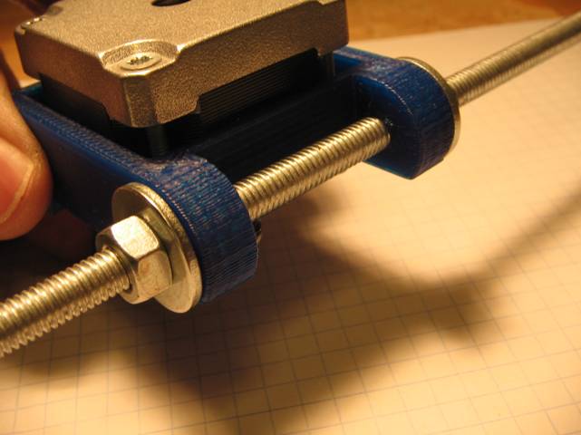
Insert an M6 washer and thread an M6 nut at each end of the support holes. Don't tighten the nuts yet.
Then thead an M6 nut about 30mm at one end of the rod. Add also an M6 washer and introduce the rod into the shaft support of the right side of the printer base (as shown in following picture). Then put another washer and a another M6 nut.
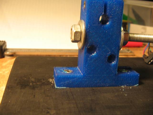
At the other end of the rod, thread an M6 nut a washer and another shaft support. Then add another washer and other M6 nut. For the moment don't screw this support to the printer base (anyway you don't have holes).
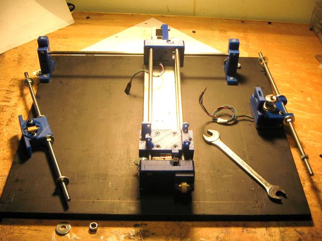
The set-up will look like this:
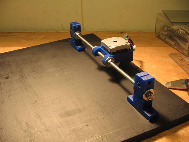

You will continue with the other part of the framework, which contains the X-belt tensioner. Introduce the tensioner support on the threaded rod with washers and M6 nuts as you did with the motor support in the other threaded rod.
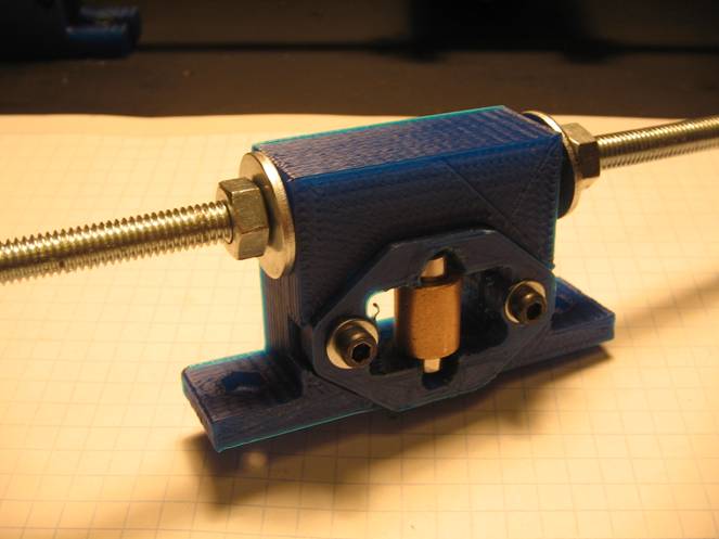
Then install the threaded rod into the shaft supports in a similar way you did it with the other threaded rod. The X-belt tensioner and pulley should be facing outward from the base.
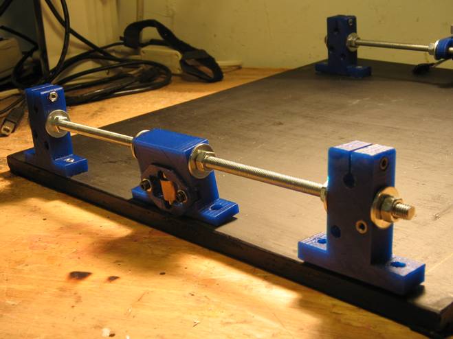
The framework will now look like this:

It is time to insert the two 6mm x 327mm steel shafts in the shaft supports jaws making sure that the supports are aligned and the framework squared.

Assembling the Printer Framework (II)
Parts required:
|
Quantity |
Material |
|
|
4 |
Printing bed supports |
|
|
1 |
Flat cable clamp |
|
|
1 |
X-Axis Belt Clamp - Split1 |
|
|
1 |
X-Axis Belt Clamp - Split2 |
|
| 1 |
T2.5 x 730mm timing belt |
|
|
1 |
Arduino UNO |
|
|
1 |
M3 x 30mm Binding Head bolt |
|
|
5 |
M3 x 17mm Socket Head Cap Screw Allen Bolts |
|
|
2 |
M3 x 9.5mm Socket Head Cap Screw Allen Bolts |
|
|
2 |
TM3 x 8mm Socket Head Cap Screw Allen Bolts |
|
|
8 |
M3 nuts |
|
|
1 |
Some oil drops |
|
Now you will install the printing bed supports.
Insert them into the slots of the four shaft supports (as shown in the picture below). The supports must be installed toward the outside of the printer. We need to install them now to tighten the jaws as they fill the gap in them.
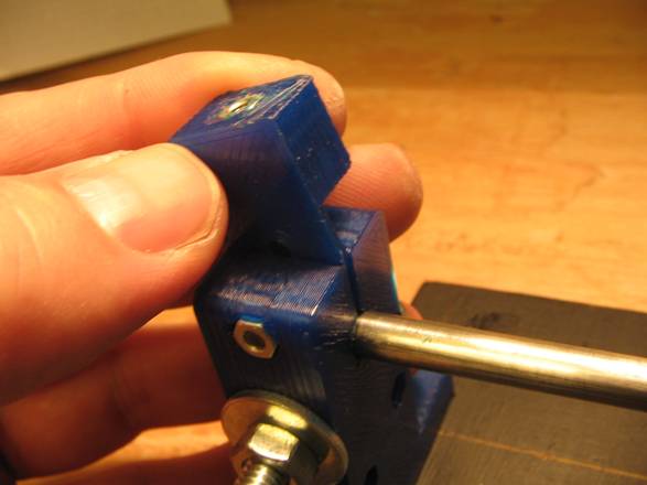
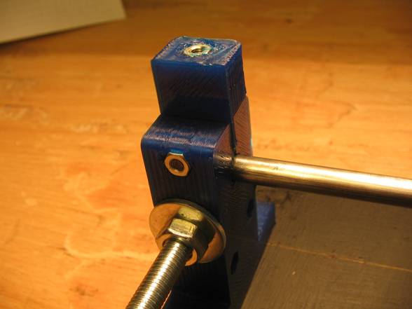
Now you will introduce the Y-gantry into the X-axis shafts.
First tighten the M6 nuts of the left shaft supports (which are bolted to the printer base). The M6 nuts of the other supports (right shaft) have to be loose so you can indroduce the Y-gantry.

Then add some oil drops on the X-axis shafts, push them out from their supports and introduce them through the Y gantry bronze bearings. First introduce the shaft of the bolted supports. Then the other shaft. Make sure that the Y-belt side of the gantry points towards the X-axis motor.


When inserting the other shaft adjust if needed (loosening the M6 nut) the shafts supports which are not bolted to the printer base.

The set-up will look like this:

Then tighten the jaws of the shaft supports.

Now you have to fix the distance between the X-axis shafts.
Push the Y-gantry carefully up to X-axis belt tensioner side of the printer.

Then adjust the M6 nuts of the unbolted shaft support (at that side of the printer) while slideing a litle the gantry from time to time until it slides smoothly through the X-axis shafts at that side of the printer.
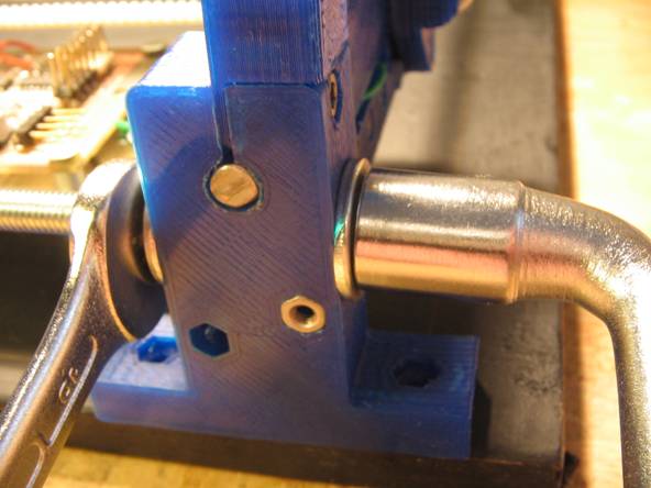
When you see that the Y gantry slides smoothly, push it to the other end of the printer and adjust the shaft distance at that side.
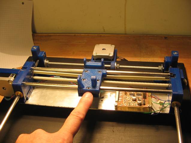
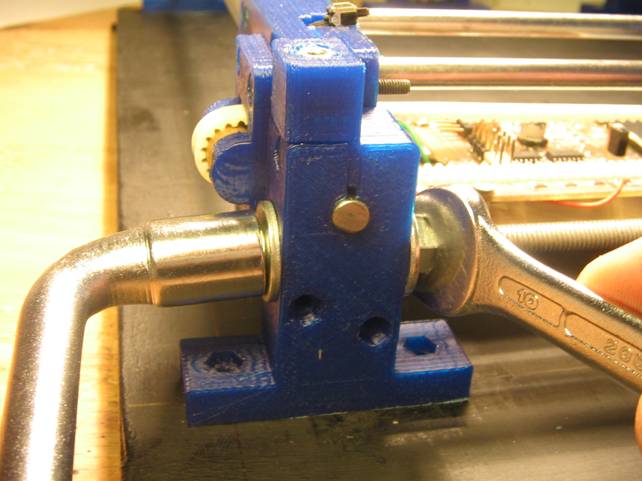
At this stage the gantry will not slide as well as desired. It is because we have not yet adjusted accurately the distance between the X-axis shafts. The important thing is that it slides more or less without too much friction along the shafts.
You will start with the shaft support of the X-axis tensioner side. Check with a square ruler that the shafts form right angles with the threaded rod adjusting the shaft support if needed. Now mark with a punch the holes of the shaft support base.


Push the gantry to the left side of the printer and check that shafts form right angles there. Mark with a punch the holes of the shaft support of that printer side.


Now you will install the X-axis belt and adjust the X-axis motor/tensioner positioning.
Take the two splits of the X-belt clamp and four bolts: two M3 x 8mm and two M3 x 9.5mm.
Insert the M3 nuts with the soldering iron in the nut-housings.
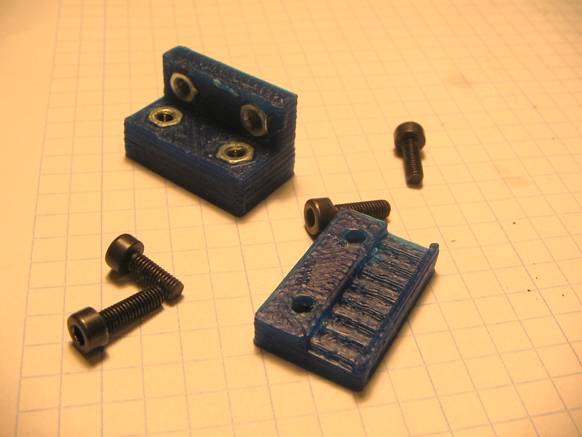
With the allen key and 2 x 8mm bolts, screw slightly the split B to the A (as shown in the picture below).
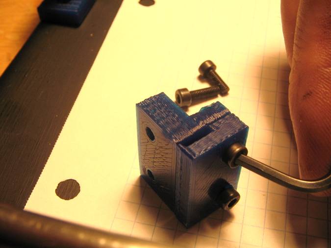
Then introduce one end of the X-axis belt into the left side of the tensioner window, toothed side toward the bronze bushing. Run the belt over the bushing and pull it away until the belt's end will be more or less at the half of the X-axis.
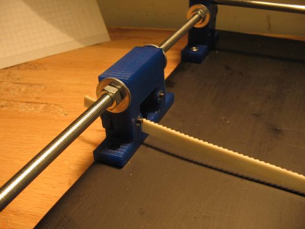
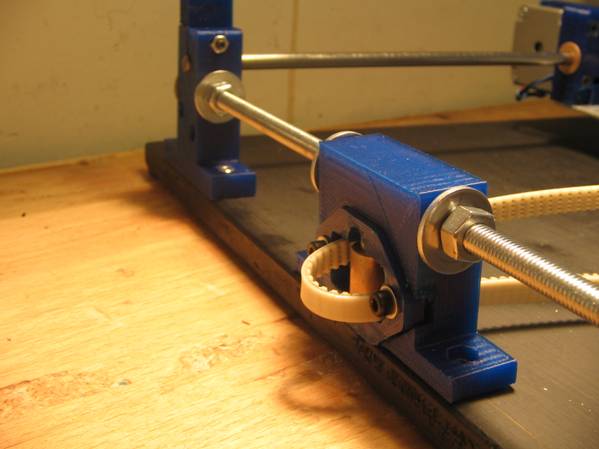
Then run the other belt end over the motor pulley until both belt ends more or less touch at the midle of the X-axis. The belt should now form an elongated loop with the teeth on the inside of the loop.

Then slide both ends of the belt into the belt clamp by pushing from both sides. If you can't insert the belt unscrew the clamp bolts slightly.
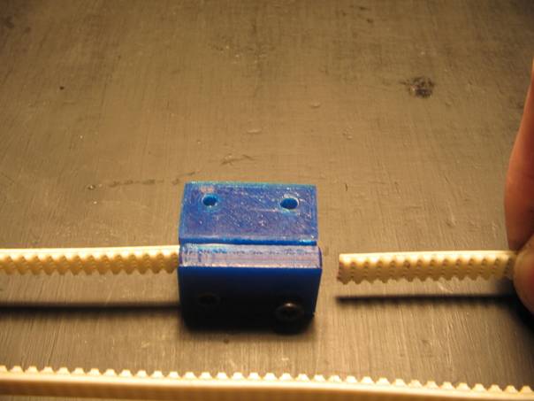
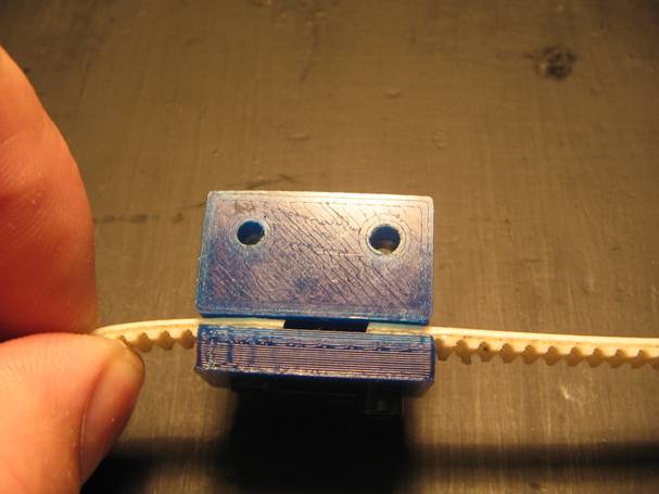
Then you have to tighten the screws with an allen key. First tighten one bolt until the belt does not slide, then tension the belt a little by introducing the other end into the clamp and tighten the other bolt till the belt will not slide out.
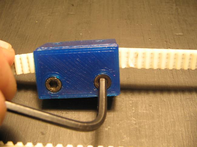
The belt will look more or less like this:
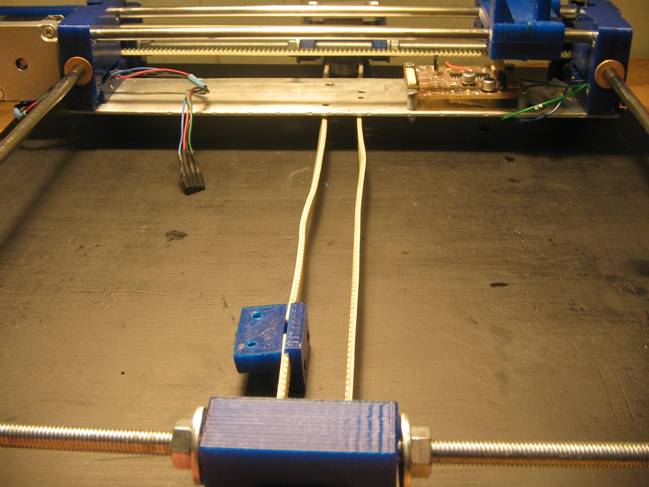
Now bolt the belt clamp to the aluminum plate of the Y gantry with two M3 x 9.5mm bolts.
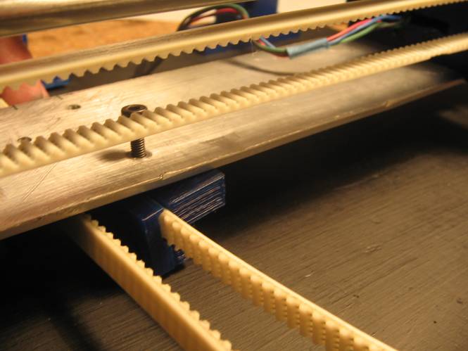
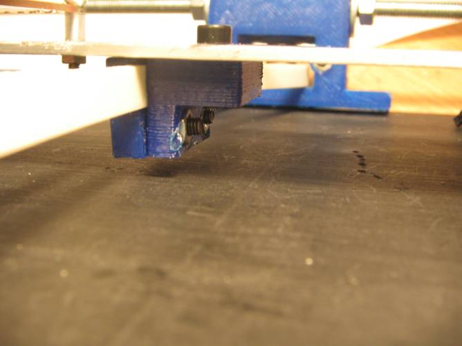
Now is time to center the tensioner, the motor and belt in order to mark the holes for the screws that bind the setup to the printer base.
First, center the tensioner by loosening the M6 nuts and moving it lefft and/or right until the belt will be aligned with the Y gantry attachment.
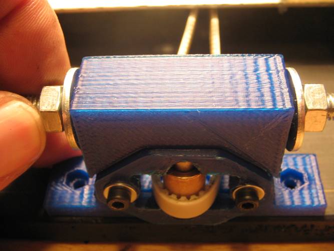

Then center the x-motor mounting.
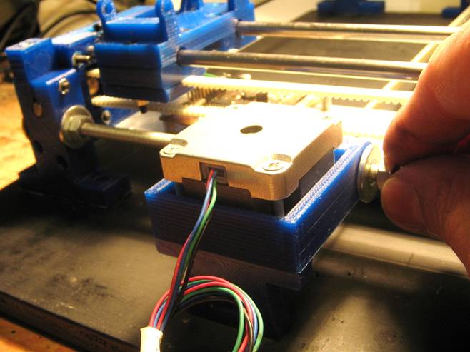
Check that the belt is straight and aligned by sliding the Y-gantry from one end to another. Then tightten the M6 nuts of the motor mounting and tensioner support.
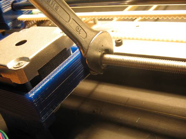
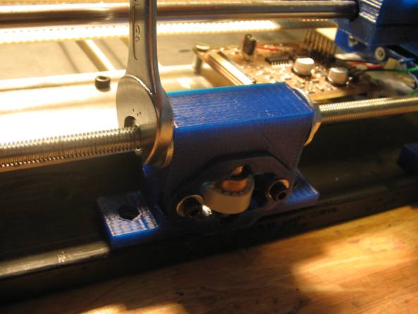
Mark with a punch and a maker pen the holes of the tensioner and motor support bases.
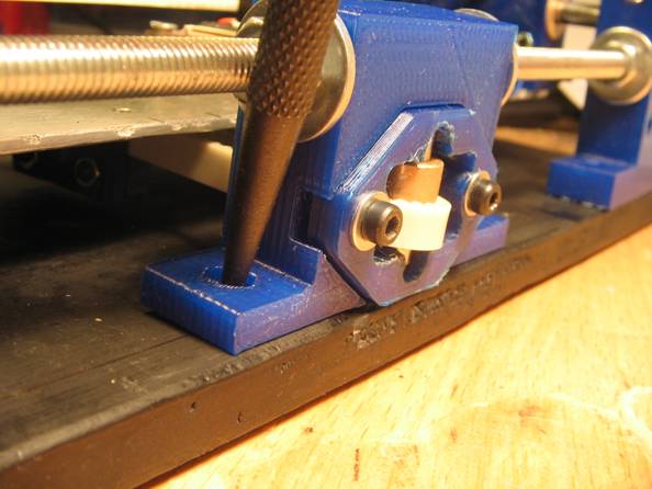
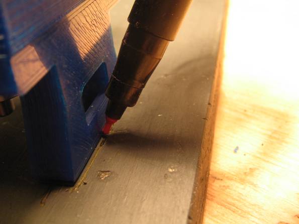
Finally mark the holes where you will screw the Arduino. Place it between the X-motor and the right X-axis shaft support, as shown in the following picture. Then mark the holes with a marker pen.
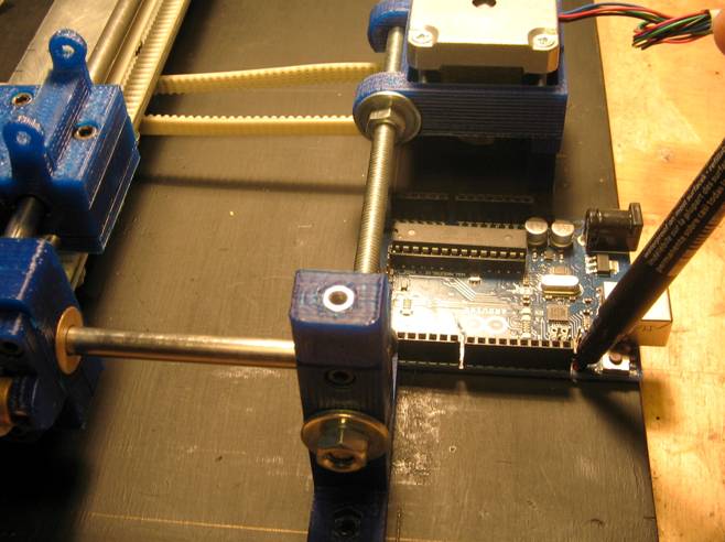
Now unistall the belt, the threaded rods and the right X-axis shaft to drill the holes.
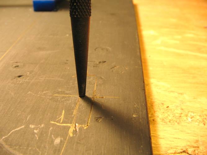
Mark with a punch the approx. position of the X-motor support bolt (at half way of the mark you did with the maker pen).
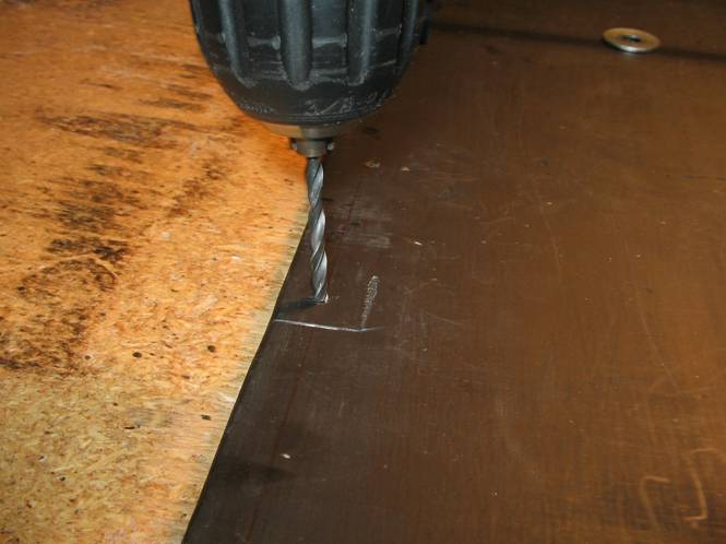
Then drill out all the marked holes with a 3mm drill bit.
Once you've drill all the holes in the printer base, you can screw the X-axis shaft suppports to the printer base with 4 x M3 x 19mm bolts. Use 2 x M3 x 15mm bolts for the tensioner support and 1 x M3 x 20mm for the X-axis motor mount.
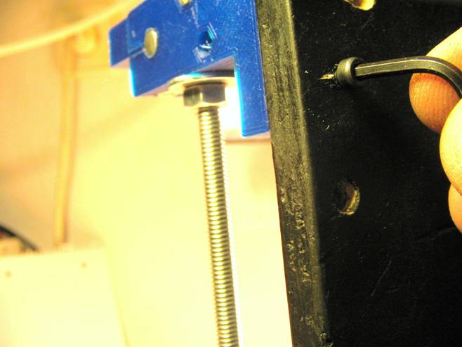
The motor support bolt need a M3 washer and a nut as shown in the picture below.
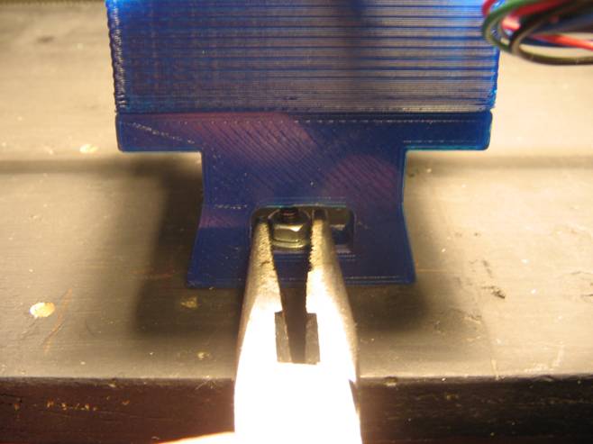
Before you will install the X-belt again you must adjust with more precision the distance between the X-axis shafts until the Y-gantry slides smoothly.
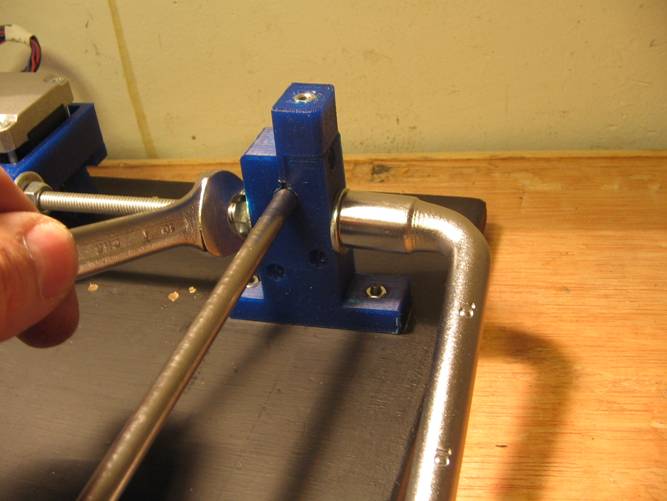
Then install the X-belt and tight it moderately by loosening little by little both tensioner screws.

Adjust the height of the motor pulley by loosening the grub screw with an M2 allen key. Don't forget to carefully tighten it again.

Then verify that the belt tension is right. Turning the motor pulley by hand should make the carriage move. The carriage should move freely along the entire length of the X-axis.
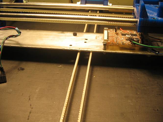
Install the ribbon cable clamp. You have to replace one of the carriage bolts by another of 17mm and bolt the clamp to the carriage.
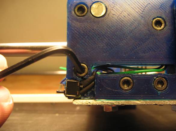
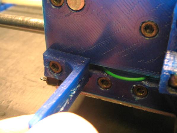
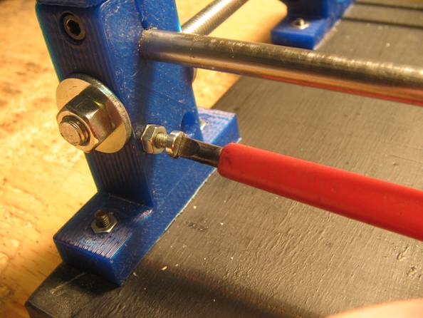
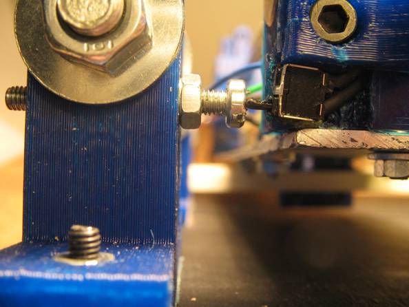
Thread the bumber screw of the x-axis end-stop microswitch to the shaft support closed to the "home position". It's a flat head M3 screw that will help you to regulate the home position of the X-axis.
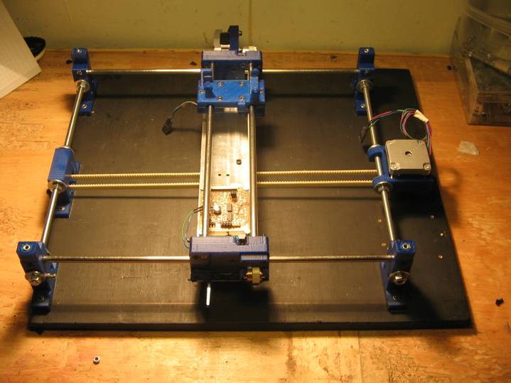
You have assembled the printer framework. Will look more or less as this:
Finally, it is recommended that you glue four pieces of anti-slip material below the printer base. This will avoid that the printer slides, and also help to ensure that the bolt heads do not chafe on the table.


